
Service manual


SECTION TSM 845.1 ISSUE C PAGE 12 OF 13
TROUBLESHOOTING
Some of the following may help pinpoint the problem:
Pump does not pump:
• Pump has lost its prime from air leak or low level in tank.
• Suction lift is too high
• Pump is rotating in the wrong direction
• Suction and/or discharge valves not open.
• The strainer may be clogged.
• The bypass valve is open, the pressure relief valve is set
too low or the pressure relief valve poppet stuck open.
• Improper end clearance
• The pump is worn out.
• Are there any changes in liquid, system or operation that
would influence pump or coupling performance, e.g. new
liquid, additional lines or process changes?
• Temperature changes either in the liquid or the
environment.
• The magnetic coupling is decoupling. Changes in
application (temperature, pressure, viscosity, etc.) may
require torque beyond coupling capabilities.
Pump starts, then loses its prime:
• The supply tank is empty
• Liquid vaporizing in the suction line
• An air leak or air pocket in the suction line.
Pump is noisy:
• Pump is being starved (heavy liquid cannot get to pump
fast enough). Increase suction pipe size, reduce its length
or slow down the pump.
• Pump is cavitating (liquid vaporizing in suction line).
Increase suction pipe size or reduce its length.
• Check alignment.
• The magnetic coupling has decoupled. Shut off and restart.
Pump is not delivering up to capacity:
• The pump is starving or cavitating – increase suction pipe
size or reduce length or reduce pump speed.
• The strainer is partially clogged.
• An air leak somewhere in suction line.
• The pump may be running too slow. Is motor the correct
speed and wired up correctly?
• The pressure relief valve is set too low, stuck open or has
a damaged poppet or seat.
• The bypass line around the pump is partially open.
• The pump is worn out or has too many gaskets.
Pump takes too much power (stalls motor):
• The liquid is more viscous than the unit is sized to handle.
• The system pressure relief valve is set too high.
• The coupling is misaligned.
• The bushings have frozen up or the liquid has set up in
the coupling.
IMPORTANT: In ordering parts for pressure relief valve, always
give model number and serial number of pump as it appears on
nameplate and name of part wanted. When ordering springs,
be sure to give pressure setting desired.
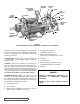
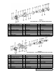
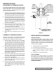
FIGURE 21
PRESSURE RELIEF VALVES
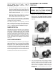
PRESSURE ADJUSTMENT
If a new spring is installed or if pressure setting of pressure
relief valve is to be changed from that which the factory has
set, the following instructions must be carefully followed.
1. Carefully remove the valve cap, which covers adjusting
screw. Loosen locknut, which locks adjusting screw
so pressure setting will not change during operation of
pump.
2. Install a pressure gauge in discharge line for actual
operating adjustment.
3. Turn adjusting screw in to increase pressure and out to
decrease pressure.
4. With discharge line closed at a point beyond pressure
gauge, gauge will show maximum pressure valve will
allow while pump is in operation.
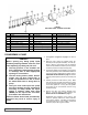
LIST OF PARTS
1. Valve Cap 6. Valve Body
2. Adjusting Screw 7. Valve Spring
3. Lock Nut 8. Poppet
4. Spring Guide 9. Cap Gasket
5. Bonnet 10. Bonnet Gasket