
Service manual


TECHNICAL SERVICE MANUAL
VIKING PUMP, INC. • A Unit of IDEX Corporation • Cedar Falls, IA 50613 USA
© 5/2007 Viking Pump Inc.
All rights reserved
SECTION TSM 845.1
PAGE 13 OF 13
ISSUE C
WARRANTY
Viking warrants all products manufactured by it to
be free from defects in workmanship or material for a
period of one (1) year from date of startup, provided
that in no event shall this warranty extend more than
eighteen (18) months from the date of shipment from
Viking. If, during said warranty period, any products
sold by Viking prove to be defective in workmanship
or material under normal use and service, and if such
products are returned to Viking’s factory at Cedar Falls,
Iowa, transportation charges prepaid, and if the products
are found by Viking to be defective in workmanship
or material, they will be replaced or repaired free of
charge, FOB. Cedar Falls, Iowa.
Viking assumes no liability for consequential
damages of any kind and the purchaser by acceptance
of delivery assumes all liability for the consequences of
the use or misuse of Viking products by the purchaser,
his employees or others. Viking will assume no field
expense for service or parts unless authorized by it in
advance.
Equipment and accessories purchased by Viking
from outside sources which are incorporated into any
Viking product are warranted only to the extent of and
by the original manufacturer’s warranty or guarantee,
if any.
THIS IS VIKING’S SOLE WARRANTY AND IS IN
LIEU OF ALL OTHER WARRANTIES, EXPRESSED
OR IMPLIED, WHICH ARE HEREBY EXCLUDED,
INCLUDING IN PARTICULAR ALL WARRANTIES
OF MERCHANTABILITY OR FITNESS FOR A
PARTICULAR PURPOSE. No officer or employee of
IDEX Corporation or Viking Pump, Inc. is authorized to
alter this warranty.
DANGER !
Before opening any Viking pump liquid
chamber (pumping chamber, reservoir,
relief valve adjusting cap fitting, etc.)
be sure:
1. That any pressure in the chamber has
been completely vented through the
suction or discharge lines or other
appropriate openings or connections.
2. That the driving means (motor, turbine,
engine, etc.) has been “locked out” or
made non-operational so that it cannot
be started while work is being done on
pump.
3. That you know what liquid the pump
has been handling and the precautions
necessary to safely handle the liquid.
Obtain a material safety data sheet
(MSDS) for the liquid to be sure these
precautions are understood.
Failure to follow above listed
precautionary measures may result in
serious injury or death.
DANGER !
Before starting pump, be sure all drive
equipment guards are in place.
Failure to properly mount guards may
result in serious injury or death.
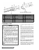
Mark valve and head before disassembly to insure proper
reassembly.
1. Remove valve cap.
2. Measure and record length of extension of adjusting
screw. Refer to “A” on Figure 21 on page 12.
3. Loosen locknut and back out adjusting screw until spring
pressure is released.
4.
Remove bonnet, spring guide, spring and poppet from
valve body. Clean and inspect all parts for wear or
damage and replace as necessary.
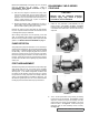
ASSEMBLY: RELIEF VALVE
Reverse procedures outlined under Disassembly. If valve is
removed for repairs, be sure to replace in original position.
Relief valve adjusting screw cap must always point toward
suction side of pump. If pump rotation is reversed, remove
relief valve and turn end for end. See Figure 3 on page 3.
Also refer to PUMP ROTATION on page 7.
DISASSEMBLY: RELIEF VALVE