
Service manual

SECTION TSM 845.1 ISSUE C PAGE 6 OF 13
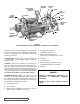
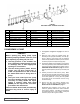
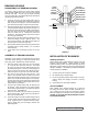
DISASSEMBLY: PUMP
1. See Figure 5 or Figure 6 on page 5 for name of
parts.
2. Mark the head, casing and bracket before dis-
assembly to insure proper reassembly. The idler pin,
which is offset in pump head, must be positioned
toward and equal distance between port connections
to allow for proper flow of liquid through pump.
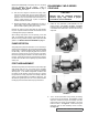
3. Unless there appears to be something wrong with the
relief valve (if present), leave assembled and attached
to the pump head. If disassembly is required, refer to
PRESSURE RELIEF VALVES on page 12.
Remove
the pump head capscrews (LQ & LS) or the nuts (Q &
QS).
4. Carefully remove the head from the pump. Make
sure the idler does not slide off the idler pin by tilting
the pump head back while removing. Avoid damage
to the head gasket set or O-ring since all gaskets
are required to set end clearance and the O-ring
enhances sealing.
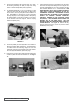
5. Remove the idler and bushing assembly from
idler pin. If the idler bushing needs replacing, see
INSTALLATION OF BUSHINGS on page 9.
Disassembly and inspection of the pump in this
manner is generally sufficient for routine evaluation
of the pump’s condition. If the idler pin and bushing
are original parts and in good condition, usually the
rest of the pump is also in good condition.
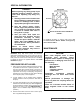
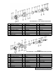
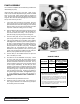
FIGURE 7
EXPLODED VIEW – D SERIES COUPLING
ITEM DESCRIPTION ITEM DESCRIPTION ITEM DESCRIPTION
1 Locknut 9 Jack Screws 17 Outer Magnet Assembly
2 Lockwasher 10 Set Screws 18 Bracket
3 Endcap 11 Insert 19 Temperature Monitor (Optional)
4 Lip Seals 12 Capscrews, Bearing Housing 20 Pipe Plug
5 Bearing Spacer, Outer 13 Grease Fitting 21 Capscrews for Canister
6 Tapered Roller Bearing, Outer 14 Bearing Housing 22 Canister
7 Bearing Spacer, Inner 15 Gasket, Bearing Housing 23 Washer
8 Tapered Roller Bearing, Inner 16 Key 24 Inner Magnet Assembly
DANGER !
Before opening any Viking pump liquid
chamber (pumping chamber, reservoir, relief
valve adjusting cap fitting etc.) Be sure:
1. That any pressure in the chamber has
been completely vented through suction
or discharge lines or other appropriate
openings or connections.
2. That the driving means (motor, turbine,
engine, etc.) has been “locked out” or
made non-operational so that it cannot
be started while work is being done on
pump.
3. That you know what liquid the pump
has been handling and the precautions
necessary to safely handle the liquid.
Obtain a material safety data sheet
(MSDS) for the liquid to be sure these
precautions are understood.
Failure to follow above listed precautionary
measures may result in serious injury or
death.