
Service manual

SECTION TSM 845.1 ISSUE C PAGE 7 OF 13
Before further disassembly of the pump can occur, the pump
must be separated from the coupling. Refer to
DISASSEMBLY: MD-D SERIES COUPLING on page 7
before proceeding with step 6.
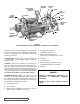
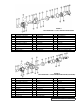
6. After the inner magnet is removed from pump shaft,
remove the external snap ring from pump shaft (LQ &
LS only). The rotor and shaft may now be removed by
tapping on the end of shaft with a soft face hammer or, if
using a regular hammer, use a piece of hardwood
between the shaft and hammer.
7. Because the balance plate is designed to be used in
either rotation, mark the balance plate prior to removal.
Remove balance plate by pulling out of casing.
Examine the casing for wear, particularly the area between
the ports. All parts should be cleaned and checked for wear
or damage before pump is assembled.
When making major repairs, such as replacing a rotor and
shaft, it is advisable to also install a new head and idler pin,
idler and bushing, bracket bushings, balance plate and head
gaskets. See INSTALLATION OF BUSHINGS on page 9.
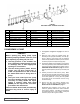
PUMP ROTATION
Viking Mag Drive
®
pumps are directional. If it is necessary to
rotate in the opposite direction, the pump must be disassembled
through step 7. Rotate the balance plate 180º and reinstall
into the casing. Second, the pipe plug (item 23 for LQ & LS,
item 24 for Q & QS) must be on the suction side of the head.
Remove the pipe plug and reinstall in the other similar hole in
the head Follow the procedure for pump assembly. Reverse
the relief valve orientation so the adjusting cap points towards
suction port.
PORT ARRANGEMENT
Standard configuration (as viewed from the pump shaft) is right
angle porting (LQ, LS & Q) – the suction port for clockwise
rotation is at 9 o’clock. The top port (at 12:00) is the standard
discharge port. If the desired configuration is different and
the rotation is still clockwise, mark the suction port, remove
the (8) bracket to casing capscrews and carefully rotate the
casing on the bracket pilot then reinstall the capscrews. The
QS features opposite ports and can not be rotated because
the flanged ports will interfere with the pump bracket foot.
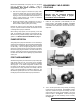
DISASSEMBLY: MD-D SERIES
COUPLING
.
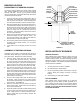
1. Install the two jackscrews (2-297-022-999) into the
bearing housing. See Figure 7 on page 6, and Figure
8. Remove two 0.50” capscrews and thread a 0.50” NC x
8” threaded rod into these holes. Remove other two 0.50”
capscrews.
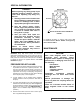
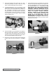
2. Turn in the two jackscrews evenly, backing the bearing
housing away from the bracket. See Figure 8. Install a
strap from overhead to support the housing and outer
magnet when the housing is approximately 1.50” away
from the bracket. See Figure 9. Continue turning the
jackscrews until the outer assembly comes out freely.
See Figure 10.
FIGURE 8
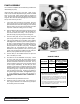
CAUTION !
Magnet sets are extremely powerful.
Serious injury may result if proper
procedures are not followed.
FIGURE 9
FIGURE 10