
Service manual

SECTION TSM 845.1 ISSUE C PAGE 8 OF 13
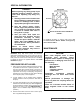
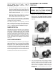
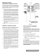
4. To facilitate disassembly, it may be necessary to slide
a block of wood under the pump casing or clamp pump
foot as shown, since the pump alone will not balance on
foot. See Figure 11. Remove the (4) 0.50” capscrews
securing the pump to the coupling bracket. After parting
the bracket slightly, it will have a tendency to be drawn
to one side due to the inner magnet. Pull the coupling
bracket completely away.
5. There will probably be some liquid left in the canister so
take the necessary safety precautions. The canister drain
is located behind the mounting flange and near the
underside. Removing plug will drain most of the canister.
Once the liquid has drained, replace the plugs.
3. Set the outer assembly with magnets down on a clean,
flat surface (preferably not steel) to keep from rolling
around. Remove temperature probe (if present).
FIGURE 11
FIGURE 12
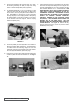
FIGURE 13
FIGURE 14
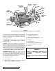
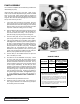
7. Insert a brass bar through a port between two rotor teeth
and loosen the capscrew holding the inner magnet onto
the shaft. See Figure 13. The 0.437” capscrew has right
hand threads therefore turn it counterclockwise. THE
INNER MAGNET HAS A VERY STRONG MAGNETIC
FIELD AND IS MOST DANGEROUS IN THE UN-
ASSEMBLED CONDITION. THE MAGNET IS QUITE
HEAVY AND WILL BE DRAWN TO ANY FERROUS
OBJECT OR SURFACE CAUSING POTENTIAL
PINCHING. BEWARE OF THE CAUTIONS LISTED
ON (PAGE 3). USE EXTREME CARE SLIDING THE
MAGNET OFF OF THE PUMP SHAFT. SET THE
MAGNET DOWN ON EITHER END AWAY FROM ALL
OTHER OBJECTS. See Figure 14. Remove the key
and the external snap ring (LQ & LS) and then finish
disassembly of the pump.
6. Remove the (8) 0.375” Allen head capscrews holding the
canister in place then slide the canister off. See Figure
12.