
Service manual

SECTION TSM 845.1 ISSUE C PAGE 9 OF 13
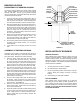
BEARING HOUSING
DISASSEMBLY OF BEARING HOUSING
The bearing housing features two grease packed tapered
roller bearings (TRB) along with a one-piece outer magnet
assembly with shaft. The unit may be greased externally
using the grease fitting. See Figure 15 if further assembly is
required and proceed as follows:
1. Cover the open end of the outer magnet with a piece of
sheet metal. This will keep foreign material out of magnet
area and protect the magnets. Set the assembly face
down with the shaft pointing up and remove jackscrews.
2. Bend the lockwasher tab up and gently tap the locknut in
a counterclockwise direction with a punch until loose. (If
this does not work, place a key into shaft of outer magnet.
Use 1.875” wrench to hold outer magnet and a spanner
wrench to loosen lock nut. Remove the locknut and
lockwasher. Then lift the bearing carrier off the shaft of
the outer magnet assembly.
3. Back out the (2) setscrews holding the bearing cap then
remove the bearing cap with a spanner wrench. The
inner and outer spacers, outer TRB and inner TRB cone
should all slide out of the bearing housing.
4. One lip seal is pressed into the bearing cap and the other
is pressed into the bearing housing. Do not remove
unless replacing.
5. If inner TRB is worn or damaged, remove cup of inner
TRB.
ASSEMBLY OF BEARING HOUSING
Depending on the condition of the bearings either replace or
recondition existing bearings by cleaning and packing with a
heavy duty grease. Replace the lip seals if necessary.
1. Place the bearing carrier down with the cast surface
up. Install the inner lip seal (if removed). Then install
the cup (if removed) of the inner TRB and the cone into
the bearing housing bore. Insert the inner bearing spacer
(longer one of the two) and the outer TRB into the bore.
Place outer spacer on top of the cone of the outer TRB.
2. The outer end cap houses the second lip seal. If the
seal is in good condition, slide the endcap over the outer
spacer then thread into bearing housing. Center the inner
spacer so the shaft will slide through the two bearings.
Thread in the end cap until it makes contact with the outer
TRB. Tighten the endcap by hand until tight and secure in
position with the (2) setscrews.
3. Insert the outer magnet shaft through the bearings and
the spacers. When the shaft is in the proper position
there should be approximately 0.75” between the magnet
and the housing. See Figure 15.
4. Place the lock washer onto the shaft then thread the
locknut onto the shaft. Tighten locknut to 50 Ft-Lbs then
bend over a lockwasher tab.
5. Tighten the endcap to 75 Ft-lbs and rotate bearing housing
2-3 turns. Back off the end cap and then retighten to 75
Ft-Lbs. Tighten the two .31” setscrews onto the endcap.
Use the grease fitting to fill the bearing chamber with
additional grease.
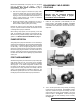
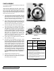
INSTALLATION OF BUSHINGS
CARBON GRAPHITE:
When installing carbon graphite bushings, extreme care must
be taken to prevent breaking. Carbon graphite is a brittle
material and easily cracked. If cracked, the bushing will quickly
disintegrate. Using a lubricant on the bushing and mating part
will help in installation. The additional precautions listed below
must be followed for installation:
1. An arbor press must be used for installation.
2. Be certain bushing is started straight.
3. Do not stop pressing operation until bushing is in proper
position, starting and stopping will result in cracking
bushing.
4. Check bushing for cracks after installation.
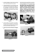
SILICON CARBIDE:
When installing silicon carbide bushings into a metal part
the mating part must be heated to 600ºF (preferably in an
oven). Bushing must be quickly put into the proper position
before the mating part cools down and the bushing heats up.
FAILURE TO FOLLOW THIS PROCEDURE WILL RESULT
IN CRACKED BUSHINGS.
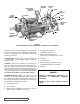
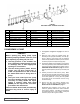
FIGURE 15
COVER END OF MAGNET
WITH PIECE OF SHEET
METAL APPROX. 10” x 10”
OUTER
MAGNET
ASSEMBLY
OUTER
SPACER
BEARING
HOUSING
OUTER BEARING
SET SCREWS (2)
LOCK WASHER
LOCK NUT
END CAP
LIP SEAL
.75 REF
INNER SPACER
GREASE FITTING
INNER BEARING