
Product manual


Wiring
IMPORTANT: Electronic devices are susceptible to lightning and power station electrical surges from both the AC
outlet and the telephone line. It is recommended that a surge protector be installed to protect against such surges.
* Gel-Filled Butt
Connectors (included)
Note: Polarity Sensitive!
(-) Black with
Red stripe
120V AC
(+) Red with
Black stripe
(+) Black
(-) Black with
White stripe
Black w/Red stripe
Red with Black stripe
Red
Black
green
Orange
Purple
Yellow
White
White
Blue
Blue
Gray
Brown
Green w/ Yellow Stripe
Red w/ Yellow Stripe
Normally Closed
Common
Normally Open
4.60
2.50
2.84
1.50
0.6
1.05
2.0
2.75
4.4
4.0
12V DC
adapter
(included)
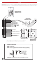
Control Module
12VDC Output
(Strobe Light Power)
Auxiliary
Relay
Contacts
Switched 12VDC Output
(to green SL-2 control lead)
Trigger Input
Disable/Info Switch Input
To Terminal Device/Phone
To C.O. Line or Analog
PABX/KSU Station
12VDC Input
8
7
6
5
4
3
2
1
8
7
6
5
4
3
2
1
Internal View of the
Weatherproof Single
Gang Box (included)
Side View of the
Strobe Light (included)
Back View of the
Weatherproof Single
Gang Box (included)
(+) Black
(-) Black with
White Stripe
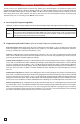
Step 1. Step 2. Step 3.
IMPORTANT: Do NOT plug in the adapter until after Step 3 is completed.
Preparing the Power Supply
Connect power supply
wires to LDB-3 module
power supply wires
Step 1. Cut off the barrel connector.
Step 2. Seperate wires
Step 3. Connect 12V adapter wires to power supply wires on LDB-3 Control
Module using supplied Butt Connectors and then plug in power supply
See "Preparing the Power
Supply" below.
* Note: The gel-filled (water tight) butt connectors are designed for
insulation displacement. Do not strip wires prior to terminating.
2