
Product manual


2. Loop/Off-hook Indication Only
The control module must be placed between the phone line and the phone/terminal device to be monitored.
Connect the incoming line to the red and green wires with the yellow stripe and connect the phone/terminal
device to the brown and gray wires as shown.
3. Both Ring and Loop/Off-hook Indication
If the application requires ring and loop/off-hook indication, the control module must be placed between the
phone line and the phone/terminal device to be monitored. Connect the incoming line to the red and green
wires with the yellow stripe, connect the phone/terminal device to the brown and gray wires.
1. Ring Indication Only
Connect the incoming line to the red and green wires with the yellow stripe as shown in the diagram. No
phone/terminal device is required. The control module can monitor for ringing any place along the ringing line.
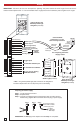
B. Configuring for Ring and/or Loop/Off-Hook Indication
(-) Black with
Red stripe
120V AC
(+) Red with
Black stripe
(+) Black
Red (+)
Black (-)
Green
Rear View of the SL-2
Strobe Light (included)
Red with
Yellow stripe
Green with
Yellow stripe
Brown
Gray
BLK-4 Control Module (included)
Auxiliary Relay Contact Output
Blue
Blue
Incoming Analog
Phone Line
Phone or
Terminal Device
(not included)
Purple
Orange
Yellow
12V DC
Adapter
(included)
(-) Black with
White stripe
White
White
Trigger Input for Optional
Remote Trigger Switch
(see Programming section G)
Disable Feature
(see Programming section F)
Note: Not polarity
sensitive.
Note: See "Preparing the
Power Supply" on page 2.
* Gel-Filled Butt Connectors
* Note: The gel-filled (water tight) butt connectors are designed for insulation displacement. Do not strip wires prior to terminating.
1
23
4
ON
BLK-4 Control Module
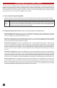
Programming the BLK-4 Control Module
A. DIP Switches
Switch 1
Switch 3
Description
ON
OFF
Ring Detection Only (see section B).
OFF
ON
Off-Hook/Loop Current Detection Only
(see section B).
ON
ON
Ring and Off-Hook/Loop Current Detection
(see section B).
Switch 2 Ring Cadence Mode (see section C)
ON
Ring Cadence Mode ON - relay remains activated in
between rings.
OFF
Ring Cadence Mode OFF - relay is activated only dur-
ing ringing.
Switch 4 Auxiliary Relay Contacts
ON Wet (12VDC, 100mA maximum)
OFF Dry (1 Amp maximum @ 30VDC)
4
DIP Switch 4 OFF
DIP Switch 4 ON
N.C.
+12VDC Normally ON
COM
+12VDC
N.O.
+12VDC Normally OFF