Viking Use/Installation Guide Combination Beverage Center/ Ice Maker Viking Range Corporation 111 Front Street Greenwood, Mississippi 38930 USA
Retain for Future Reference IMPORTANT - PLEASE READ AND FOLLOW • • • • • Before beginning, please read these instructions completely and carefully. Do not remove permanently affixed labels, warnings, or plates from the product. This may void the warranty. Please observe all local and national codes and ordinances. Please ensure that this product is properly grounded. The installer should leave these instructions with the consumer who should retain for local inspector’s use and for future reference.
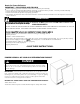
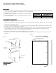
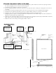
UNDERCOUNTER CABINET CUTOUT A 24” (61.0 cm)* B Min. 34 1/2” (87.6 cm) A Max. 35 1/8” (89.2 cm) C C B 24” (61.0 cm) * *24” width for cabinet only. 24 1/4” (61.6 cm) need for cabinet and door width clearance if door is recessed between cabinets. *Optional: Cutout for electrical outlet can be placed in adjacent cabinetry. SPECIFICATIONS/DIMENSIONS PROFESSIONAL SERIES Basic Electric Data •115 VAC/60 Hz •Maximum amps - 3.3 •Approximate Shipping Weight - 140 lbs. (63.2 kg) 30 3/4” (78.1 cm) Min.
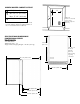
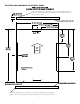
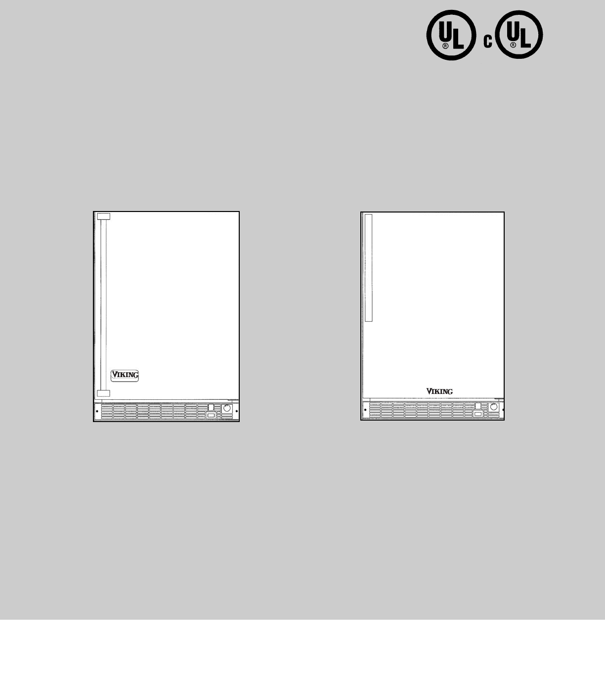
SPECIFICATIONS/DIMENSIONS DESIGNER SERIES Front View Basic Electric Data •115 VAC/60 Hz •Maximum amps - 3.3 •Approximate shipping weight - 140 lbs (63.2 kg) Mín. 34 1/4” (87.0 cm) Max. 35” (88.9 cm) with leveling legs fully extended 30 3/4” (78.1 cm) 23 7/8” (60.6 cm) Side View 47 1/4” (120.0 cm) 22” (55.9 cm) 24 3/8” (61.9 cm) 25 3/8” ( 64.
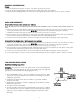
GENERAL INFORMATION Unpack 1. Remove banding from bottom of carton. Lift carton up and off of the unit. 2. Remove all tape and packaging material from the outside and inside of the cabinet. 3. Keep all carton packaging until your unit has been thoroughly inspected and found to be in good condition. AREA REQUIREMENTS Units Certified for Indoor Use - (black outer cabinet) MUST BE INSTALLED IN AN AREA PROTECTED FROM THE ELEMENTS, SUCH AS WIND, RAIN, WATER (SPRAY OR DRIP). 1.
FULL OVERLAY PANEL INSTALLATION Note: Weight of wood panel must not exceed 20 lbs. Wood Screws 1. A #8 pan head wood screw should be used to properly secure the wood frame. A total of 10 screws will be needed for a 3 1/2” (8.9 cm) kickplate or 8 screws for a 4” (10.2 cm) kickplate. 2. Only use pan head screws. Working Material Wood Screw Size #8 3. DO NOT select a screw that is longer than the wood thickness at Hardwood 3/32 (0.24 cm) the screw locations. Softwood 5/64 (0.20 cm) 4.
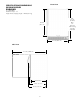
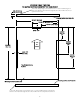
SELECTING AND PREPARING THE OVERLAY PANEL FOR A 3-1/2” TOE KICK (COVERS THE ENTIRE DOOR EXTRUSION) 1/4” x 3/8” Deep hinge screw clearance hole. Locate and drill using door hinge hole after the door has been aligned to the unit and when the wood is positioned on door. Min. 5/8” (1.7 cm) Max. 3/4” (1.9 cm) Mounting surface (non-face) side 23 3/4” (60.3 cm) 17 15/16” (45.6 cm) TYP 5 13/16” (14.8 cm) 23/32 “ TYP 5 23/32” (14.6 cm) TYP 15 5/32” (38.5 cm) TYP TOP OF DOOR 30 5/16” (77.
OPTIONAL FOR 4” TOE KICK TO MATCH EXISTING CABINETRY TOE KICK HEIGHT 1/4” x 3/8” Deep hinge screw clearance hole. Locate and drill using door hinge hole after the door has been aligned to the unit and when the wood is positioned on door. Min. 5/8” (1.7 cm) Max. 3/4” (1.9 cm) Mounting surface (non-face) side 23 3/4” (60.3 cm) 17 15/16” (45.6 cm) TYP 5 13/16” (14.8 cm) 23/32 “ TYP 5 23/32” (14.6 cm) TYP 15 5/32” (38.5 cm) TYP TOP OF DOOR 29 13/16” (75.7 cm) 13/16” TYP Both Sides 24 1/2” (62.
ATTACHING THE OVERLAY PANEL TO THE DOOR 1. If the door is attached to the unit, remove by unscrewing the top allen head set screw at the top hinge. Remove the door by angling the door off of the bottom hinge pin. 2. Peel back the door gasket to expose the screw holes. 3. Set the overlay panel flush to the front of the door in the desired location. Clamp the overlay panel to the door if necessary. 4. Insert the wood screws through the back of the door into the pilot holes in the overlay panel and tighten. 5.
ELECTRICAL CONNECTION WARNING ELECTRICAL SHOCK HAZARD Failure to follow these instructions could result in fire or electrical shock. Electrical Requirements A 115 volt, 60 Hz, AC only 15 amp fused electrical supply is required. (A time delay fuse or circuit breaker is recommended.) It is recommended that a separate circuit, serving only this appliance, be provided. Power Supply with 3-prong grounding plug Grounding type wall receptacle •ELECTRICAL GROUND IS REQUIRED ON THIS APPLIANCE.
WIRING DIAGRAM UNDERCOUNTER 24” W. COMBINATION BEVERAGE CENTER/ICE MAKER WARNING: ELECTRICAL GROUNDING INSTRUCTIONS This appliance is equipped with a three prong grounding plug for your protection against shock hazard and should be plugged directly into a properly grounded three prong receptacle. Do not cut or remove the grounding prong from this plug.
Setting the Controls The temperature control knob is located in the grille below the door. There is a pointer on the grille at the 12:00 position to indicate knob position. The “OFF” position will turn the refrigeration system off. Position 1 is the warmest setting and position 7 is the coldest. Wait at least 2 hours between temperature adjustments to find a temperature that suits you.
CAUTION The ice maker must have all water drained and removed to prevent damages as well as possible water damage to the surrounding area in freezing conditions. These damages are not covered under warranty.
LIGHT BULB REPLACEMENT WARNING Screws ELECTRICAL FIRE HAZARD Do not replace bulb with a bulb higher than 15 watts. This unit uses a 15-watt appliance bulb with an intermediate base located inside the light shield. The light shield is on the back of the unit and is held in place by the use of three screws. Remove the three screws and light shield to remove the light bulb. DO NOT replace the bulb with a bulb higher than 15 watts. Light Shield ENERGY SAVING TIPS •Reduce door openings.
TROUBLESHOOTING CHART Problem Possible Cause Odor in cabinet Interior needs cleaning. Unit operates but does not produce any ice Small ice cubes Noisy operation Ice cubes sticking together. Solution Clean the interior using a solution of baking soda and war water or water and mild soap The unit has just been started and it Typical ice production is 2 lbs per day. Allow has been less than 24 hours. for the freezer section to reach temperature and the ice maker to cycle and accumulate ice.
TROUBLESHOOTING CHART Problem Possible Cause Moisture collects on outside surface of cabinet Moisture collects inside of the unit. The unit is too warm or too cold. The unit is warm inside with the temperature control knob in the “OFF” position. Items on door shelf sometimes freeze. Solution Hot and humid conditions. Extremely hot and humid conditions can cause condensation on the outside of unit. As humidity and/or temperature decreases, condensation will disappear Too many door openings.
SERVICE INFORMATION It is assumed that your combination beverage center/ice maker has been properly installed in accordance with all specifications and local codes and the appliance has been properly grounded. If your unit should fail to operate, review the troubleshooting chart before calling for service. If service is required: 1. Call your dealer or authorized service agency. The name of the authorized service agency can be obtained from the dealer or distributor in your area. 2.
UNDERCOUNTER/FREESTANDING COMBINATION BEVERAGE CENTER/ICE MAKER WARRANTY (Units certified for Outdoor Use) ONE YEAR FULL WARRANTY Undercounter/freestanding combination beverage center/ice makers and all of their components and accessories, except as detailed below*, are warranted to be free from defects in material or workmanship under normal household use for a period of one (1) year from the date of original retail purchase.
UNDERCOUNTER/FREESTANDING COMBINATION BEVERAGE CENTER/ICE MAKER WARRANTY (Units certified for Indoor Use) TWO YEAR FULL WARRANTY Undercounter/freestanding combination beverage center/ice makers and all of their components and accessories, except as detailed below*, are warranted to be free from defects in material or workmanship under normal household use for a period of two (2) years from the date of original retail purchase.
Viking Range Corporation 111 Front Street Greenwood, Mississippi 38930 USA (662) 455-1200 For product information call 1-888-VIKNG1 (845-4641) or visit the Viking Web Site at vikingrange.