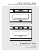
Viking Installation Guide Guide d’installation Viking / Guía de instalación Viking Setup/ Help Sensor Popcorn Sensor Reheat Sensor Cook OPEN Start Add-A-Minute 1 2 3 4 5 Power Level Control Lock Keep Warm Defrost Reheat CLOSE Stop/ Clear 6 7 8 9 0 Timer/ Clock On/Off VMOD241SS Setup/ Help Sensor Popcorn Sensor Reheat Sensor Cook OPEN Start Add-A-Minute 1 2 3 4 5 Power Level Control Lock Keep Warm Defrost Reheat CLOSE Stop/ Clear 6 7 8 9 0 Timer/ Clock On/O
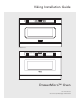
Viking Installation Guide Setup/ Help Sensor Popcorn Sensor Reheat Sensor Cook OPEN Start Add-A-Minute 1 2 3 4 5 Power Level Control Lock Keep Warm Defrost Reheat CLOSE Stop/ Clear 6 7 8 9 0 Timer/ Clock On/Off VMOD241SS Setup/ Help Sensor Popcorn Sensor Reheat Sensor Cook OPEN Start Add-A-Minute 1 2 3 4 5 Power Level Control Lock Keep Warm Defrost Reheat CLOSE Stop/ Clear 6 7 8 9 0 Timer/ Clock On/Off DMOD241SS DrawerMicro™ Oven 111 Front Street Greenwoo
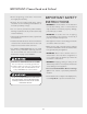
IMPORTANT–Please Read and Follow! IMPORTANT SAFETY INSTRUCTIONS • Before beginning, read these instructions thoroughly and carefully. • Because the kit includes metal parts, caution should be used in handling and installation to avoid the possibility of injury. • WARNING: If the information in this manual is not followed exactly, a fire or electrical shock may result that could cause property damage, personal injury or death.
Unpacking your DrawerMicro Oven™ Important Notes to the Installer • Remove all packing materials from inside the DrawerMicro Oven. DO NOT REMOVE THE WAVEGUIDE COVER, which is located on the top of the appliance. • Read all of the Installation Manual before installing the DrawerMicro Oven. Sealing Surface • Remove all packing material before connecting the electrical supply. Waveguide Cover • Observe all governing codes and ordinances. • Be sure to leave these instructions with the consumer.
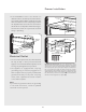
DrawerMicro Oven Measurements 1 Clearances and Dimensions Anti-Tip block 3 ¹⁄₂" 5" 22 ¹⁄₈" opening 4" Allow ¾" overlap. 36" countertop height • Dimensions that are shown in figure 1 must be used. Given dimensions provide minimum clearance. Locate electrical outlet in the shaded area in the upper left-hand corner of the cutout. See figure 4. (6") Electrical outlet location 23 ½" Allow ¾" min depth overlap.
Drawer Installation • If the DrawerMicro Oven is ever moved to a different location, the Anti-Tip block must also be moved and installed. When installed to the wall, make sure that the screws completely penetrate the dry wall and are secured in wood or metal so that the block is totally stable. When fastening, be sure that the screws do not penetrate electrical wiring or plumbing. 3 4 Electrical Outlet Location 5" (127 mm) 4" (101.
GROUNDING INSTRUCTIONS Care, Cleaning and Maintenance Refer to the Use and Care Manual for cleaning instructions. This appliance must be grounded. In the event of an electrical short circuit, grounding reduces the risk of electric shock by providing an escape wire for the electric current. The DrawerMicro Oven is equipped with a cord having a grounding wire with a grounding plug.
Guide d’installation Viking Setup/ Help Sensor Popcorn Sensor Reheat Sensor Cook OPEN Start Add-A-Minute 1 2 3 4 5 Power Level Control Lock Keep Warm Defrost Reheat CLOSE Stop/ Clear 6 7 8 9 0 Timer/ Clock On/Off VMOD241SS Setup/ Help Sensor Popcorn Sensor Reheat Sensor Cook OPEN Start Add-A-Minute 1 2 3 4 5 Power Level Control Lock Keep Warm Defrost Reheat CLOSE Stop/ Clear 6 7 8 9 0 Timer/ Clock On/Off DMOD241SS Four DrawerMicro™ 111 Front Street Greenw
IMPORTANT - S’il vous plaît lire et suivre INSTRUCTIONS DE SÛRETÉ IMPORTANTES • Prière de lire attentivement toutes ces directives avant de commencer. • Le kit comprend des parties métalliques, il faut faire attention lors de la manipulation et de l’installation pour éviter éventuelles blessures.
Déballage du Four DrawerMicro™ Remarques Importantes pour L’installateur • Retirez tout le matériau d’emballage du Dr awerMicro O ven. N’ENLE VE Z PAS LE COUVERCLE DU GUIDE D’ONDES, qui se trouve sur le dessus du Four DrawerMicro. • Lisez tout le manuel d’installation avant d’installer le Four DrawerMicro. Surface d’étanchéité • Enlevez tout le matériau d’emballage avant de connecter le secteur d’alimentation électrique. Couvercle du guide d’ondes • Obser vez tous les codes et règlement s principaux.
Dimensions du Four DrawerMicro schéma 1 Jeux et Dimensions Emplacement de prise électrique Bloc antibasculement 3 ½ po 5 po Hauteur de comptoir de 36 po 14 ¹³₁₆ po jusqu’au fond du bloc antibasculement 4po Ouverture de 22 ¹⁄₈ po Prévoir ouverture de ⁷₈ po • Les dimensions illustrées en schéma 1 devraient être utilisées. Les dimensions indiquées donnent le jeu minimum. Situez la prise électrique dans la zone tramée en haut et à gauche dans le découpé. Consultez la schéma 4.
Installation du Tiroir • Si jamais l’on choisit de changer l’emplacement du Four DrawerMicro, il faut changer l’emplacement du / réinstaller le bloc antibasculement en même temps.
INSTRUCTIONS POUR LA MISE À LA TERRE Entretien, Nettoyage et Service Il faut que cet appareil soit mis à la terre. En cas de court-circuit, la mise à la terre réduit le risque de décharge électrique en fournissant une voie d’échappement pour le courant électrique. Le Four DrawerMicro est équipé d’un cordon avec un conducteur de terre et une fiche de mise à la terre.
Guía de instalación Viking Setup/ Help Sensor Popcorn Sensor Reheat Sensor Cook OPEN Start Add-A-Minute 1 2 3 4 5 Power Level Control Lock Keep Warm Defrost Reheat CLOSE Stop/ Clear 6 7 8 9 0 Timer/ Clock On/Off VMOD241SS Setup/ Help Sensor Popcorn Sensor Reheat Sensor Cook OPEN Start Add-A-Minute 1 2 3 4 5 Power Level Control Lock Keep Warm Defrost Reheat CLOSE Stop/ Clear 6 7 8 9 0 Timer/ Clock On/Off DMOD241SS Horno DrawerMicro™ 111 Front Street Greenw
IMPORTANTE – ¡Lea y siga con atención! INSTRUCCIONES DE SEGURIDAD IMPORTANTES • Antes de comenzar, lea estas instrucciones detenida y atentamente. • El juego incluye partes de metal por lo que debe manipularlo e instalarlo con precaución para evitar el riesgo de lesiones. • ADVERTENCIA: Si no se cumple con la información contenida en este manual con exactitud, es posible que ocurra un incendio o descarga eléctrica que podría causar daño a la propiedad, lesiones personales o la muerte.
Desembalaje de su Horno DrawerMicro™ Notas Importantes Para el Instalador • Retire todos los materiales de embalaje que están dentro de la gaveta. NO RETIRE LA CUBIERTA DE LA GUÍA DE ONDAS, ubicada en la parte superior del Horno DrawerMicro. • Lea por completo el Manual de instalación antes de instalar el Horno DrawerMicro. Superficie de sellado • Retire todos los materiales de embalaje antes de conectar el suministro de energía eléctrica.
Medidas del Horno DrawerMicro (6") Ubicación del tomacorriente figura 1 Espacios Libres y Dimensiones 5" 4" Abertura de 22 ¹⁄₈" Deje un traslapo de ¾" Profundidad de 23 ½"min. Deje un traslapo de ¾" Altura del mostrador 36" • Las dimensiones mostradas en la figura 1 deben ser utilizadas. Las dimensiones suministradas proporcionan un espacio libre mínimo. Ubique el tomacorriente eléctrico en el área cubierta en la esquina superior izquierda del recorte. Vea la figura 4.
Instalación de la Gaveta • Si el Horno DrawerMicro es traslado alguna vez a otra ubicación, el bloque antivolcaduras también deber ser trasladado e instalado. Al instalarla en la pared, asegúrese de que los tornillos penetren por completo en el drywall y se aseguren en madera o metal de modo que el bloque se encuentre totalmente estable. Al ajustar los tornillos asegúrese que no perforen el cableado eléctrico o las instalaciones sanitarias. figura 5" (127 mm) 4" (101.
INSTRUCCIONES DE CONEXIÓN A TIERRA Cuidado, Limpieza y Mantenimiento Este electrodoméstico debe ser conectado a tierra. En caso que se produzca un cortocircuito eléctrico, la conexión a tierra reduce el riesgo de descarga eléctrica proporcionando una vía de escape para la corriente eléctrica. El Horno DrawerMicro está equipado con un cable que tiene un alambre de tierra y un enchufe con toma a tierra.