Installation Guide Viking Range, LLC 111 Front Street Greenwood, Mississippi 38930 USA (662) 455-1200 For product information, call 1-888-(845-4641) or visit the Viking Web site at vikingrange.
Table of Contents IMPORTANT—Please Read and Follow! Warnings & Important Information _________________________________________________________ 3 Professional Dimensions & Specifications (30” & 36”)___________________________________________ 6 Dimensions & Specifications (30” & 36” with flush mount trim) _______________________ 8 Cutout Dimensions (30”)________________________________________________________ 10 Anti-Tip Dimensions (30”) _______________________________________________________ 11 Cutout Dime
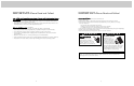
IMPORTANT—Please Read and Follow! IMPORTANT—Please Read and Follow! A GFI shall be used if required by NFPA-70 (National Electric Code), federal/state/local laws, or local ordinances. • The required use of a GFI is normally related to the location of a receptacle with respect to any significant sources of water or moisture. • Viking Range, LLC will NOT warranty any problems resulting from GFI outlets which are not installed properly or do not meet the requirements below.
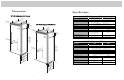
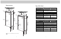
Dimensions Specifications 30” All Refrigerator/All Freezer 30” All Refrigerator/All Freezer Description 30” (73.7 c cm) 36” All Refrigerator/All Freezer 9–5/3 Cutout width Cutout height Cutout depth Electrical requirements 2” (23.3 c m) 35” 36” 3–19/ 32” (88.9 c m) (91.5 c m) (9.1 cm )) (23.3 c2” m) 82–3 75–1 (19 5/16” 2.9 c m ) (210. /4” 2 cm min. ) to /2” 26-1 cm) grounded 3-prong plug attached to product 9.1 amps 5.
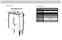
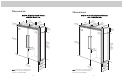
Dimensions Specifications 30” All Refrigerator/All Freezer with Flush Mount Trim 30” All Refrigerator/All Freezer with Flush Mount Trim Description Overall width 29” 30” (73.7 c Overall height from bottom Overall depth from rear m) (76.2 c m) 3–19/ 3 (9.1 2” cm) 36” All Refrigerator/All Freezer with Flush Mount Trim 9–5/3 2 (23.3 c ” m) Cutout width Cutout height Cutout depth Electrical requirements 35” 36” 3–19/ 32” (88.9 c m) Maximum amp usage Inlet water requirements (91.5 c m) (9.
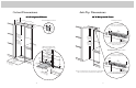
Cutout Dimensions Anti-Tip Dimensions 30” All Refrigerator/All Freezer 30” All Refrigerator/All Freezer 4” 2 cm) (61.0 See An ti- Tip bo Anti-Tip Location Electric Outlet Location ard ins ta llation 6” (15.2 cm) Two 2”x 4” mounting boards 3” (7.6 cm) x 3-1/2” (8.9 cm) 9” (22.9 cm) 9” (22.9 3” ) m cm) (7.6 c 23” (58.4 c m) 82 (210 –7/8” .5 anti- cm) mi tip n 3–1/ 79 (201 –3/8” .6 cm )m to open board . & ing h eigh t bo in. anti- ttom of tip b oard 84 (213 –1/16” .
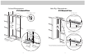
Cutout Dimensions Anti-Tip Dimensions 36” All Refrigerator/All Freezer 24” ) cm (61.0 See An ti- Tip bo 36” All Refrigerator/All Freezer Anti-Tip Location Electric Outlet Location ard ins ta llation 6” (15.2 cm) Two 2”x 4” mounting boards 3” (7.6 cm) x 3-1/2” (8.9 cm) 9” (22.9 cm) 9” (22.9 3” ) m cm) (7.6 c 29–1/2 (74.9 c ” m) 82 (210 –7/8” .5 anti- cm) mi tip n 3–1/ (8.9 c2” m) . open board & ing h eigh t 79 (201 –3/8” .6 cm )m to bo in.
Dimensions Dimensions Dual 30” & 36” All Refrigerator/All Freezer Dual 30” All Refrigerator/All Freezer 29” 29” (73.7 c 30” 3–19/ 3 (9.1 2” (73.7 c 30” m) (76.2 c m) 3 (9.1 cm2” ) 29” 30” (7 cm) 3–19/ (73.7 c m ) (76.2 c m) m) 35” 36” (88.9 c m) (91.5 c m) 6.2 cm ) 9–5/3 (23.3 c2” m) 9–5/3 (23.3 c2” m) 75–1 (192 5/16” .9 75–1 5 (192 /16” .9 cm ) cm ) 82–3 82–3 (210. /4” 2 cm min. ) to 84–1 / (213 16” (213. 16” 5 cm max. ) (210. /4” 2 cm min. ) to 2” 26-1/ ) (67.
Dimensions Specifications Dual All Refrigerator/All Freezer* Dual 36” All Refrigerator/All Freezer Description Overall width Overall height from bottom Overall depth from rear 35” (88.9 c m) 36” 3–19/ 3 (9.1 2” (91.5 c m) 36” 35” (88.9 c m) (91.5 c m) cm) Cutout width Cutout height Cutout depth Electrical requirements 9–5/3 (23 2” .3 cm) Maximum amp usage Inlet water requirements (All Freezer only) (2) 30” Units (192 5/16” .9 cm ) Approximate shipping weight 82–3 (210. /4” 2 cm min.
Dimensions Dimensions Dual 30” All Refrigerator/All Freezer with Flush Mount Trim Dual 30” & 36” All Refrigerator/All Freezer with Flush Mount Trim 29” ) 30” 3–19/ 3 (9.1 2” 29” (73.7 c m (76.2 c m) 29” 30” m) 30” (73.7 c m ) 3–19/ 3 (9.1 cm2” ) (76.2 c m) cm) (73.7 c (76.2 c m) 35” 36” (88.9 c m) (91.5 c m) 9–5/3 (23.3 c2” m) 9–5/3 2 (23.3 c ” m) 75–1 (192 5/16” .9 cm) 82–3 (210 /4” .2 cm min. ) to 2 (192 5/16” .9 cm ) 82–3 (210. /4” 2 cm min. ) to 84–1 / (213.
Dimensions Specifications Dual 36” All Refrigerator/All Freezer with Flush Mount Trim Dual All Refrigerator/All Freezer w/Flush Mount Trim* 3–19/ 3 (9.1 2” 36” (91.5 c m) 36” 60” (152.4 cm) 66” (167.6 cm) 72” (182.9 cm) 82-3/4” (210.2 cm) min. to 84-1/16” (213.5 cm) max. To front edge of side trim: 23-3/8” (59.4 cm) To front of top grille: 24” (61.0 cm) To front of handle endcap: 26-1/2” (67.3 cm) 60” (152.4 cm) 66” (167.6 cm) 72” (182.9 cm) 82-7/8” (210.5 cm) min. to 84-1/16” (213.5 cm) max.
Cutout Dimensions Anti-Tip Dimensions Dual 30” All Refrigerator/All Freezer 24” ) .0 cm (61 See An ti-Tip b oard in stallatio n Dual 30” All Refrigerator/All Freezer Electric Outlet Location Anti-Tip Location 6” (15.2 cm) 9” (22.9 Two 2”x 4” mounting boards per unit 3” (7.6 cm) x 3–1/2” (8.9 cm) 9” (22.9 cm) cm) 23” (58.4 c m) 82–7 (210 /8” anti- .5 cm) m tip b i open o n. ing hard & eigh t 73–3/ (186.4 m) 8” 79 (201 –3/8” .6 cm )m to cm) (213 / 16” . anti- 5 cm) m ti a 3–1/ (8.
Cutout Dimensions Anti-Tip Dimensions Dual 30” & 36” All Refrigerator/All Freezer Dual 30” & 36” All Refrigerator/All Freezer 24” ) .0 cm (61 See An ti-Tip b oard in stallatio n Electric Outlet Location Anti-Tip Location 6” (15.2 cm) 9” (22.9 9” (22.9 cm) Two 2”x 4” mounting boards per unit 3” (7.6 cm) x 3 1/2” (8.9 cm) cm) 82 (210 –7/8” .5 anti- cm) mi tip b n. oa open ing h rd & eigh t 29” (73.7 c 79 (201 –3/8” .6 to bo cm) min . tto 73–3 (186.4/8” cm) anti- 84 (213 –1/16” .
Cutout Dimensions Anti-Tip Dimensions Dual 36” All Refrigerator/All Freezer 24” ) .0 cm (61 See An ti-Tip b oard in stallatio n Dual 36” All Refrigerator/All Freezer Electric Outlet Location Anti-Tip Location 6” (15.2 cm) 9” (22.9 Two 2”x 4” mounting boards per unit 3” (7.6 cm) x 3–1/2” (8.9 cm) 9” (22.9 cm) cm) 29” (73.7 c m) 82– 7 / (210 .5 8” anti- cm) mi tip b n. oa o penin rd g he & ight 3” ) m (7.6 c m) / .6 8” to bo cm) min . (201 73–3/ (186.
Cabinet Information Cabinet Information Professional models fit “semi-flush” in standard 24” (61.0 cm) deep cabinet openings. The door face protrudes 1-3/4” (4.4 cm) from the cabinet face. The handle protrudes an additional 2-1/2” (6.4 cm) into the room. Professional models fit “semi-flush” in standard 24” (61.0 cm) deep cabinet openings. The door face protrudes 1-3/4” (4.4 cm) from the cabinet face. The handle protrudes an additional 2-1/2” (6.4 cm) into the room.
Cabinet Information Cabinet Information (With Flush Mount Trim) Models with flush mount trim fit flush in standard 24” (61.0 cm) deep cabinet openings with no protrusion into the room except the handle protrudes 2-1/2” (6.4 cm) into the room. (With Flush Mount Trim) Models with flush mount trim fit flush in standard 24” (61.0 cm) deep cabinet openings with no protrusion into the room except the handle protrudes 2-1/2” (6.4 cm) into the room.
Custom Side Panel Dimensions 3/16” (0.5 cm) Back filler panel 6” 1 -7/ ) 227.0 cm (5 Custom Side Panel Dimensions (With Flush Mount Trim) 3/4” (1.9 cm) End panel Z-Bracket 1/4” (0.6 cm) 4” -3/ ) 21.2 cm 6” m) .2 (15 1” (2.5 cm) c (55 3/4” 5/32” (1.9 cm) End panel (0.4 cm) 4” -3/ ) 21.2 cm ” /16) 2-7 cm 2 7.0 5 (55 ( (2182-7 0.5 /8 cm ” to ) min 8 4 (21 -1 . 3.5 /1 cm 6” )m ax .* (2182-7 0.5 /8 cm ” to ) min 8 (21 4-1 . 3.5 /1 cm 6” )m ax .* 6” m) .2 (15 (2182-7 0.
General Information Area Requirements It is required that a separate circuit serving only this appliance be provided. This appliance is equipped with a power supply cord having a 3-prong grounding plug. To minimize possible shock hazard, the cord must be plugged into a mating 3-prong, grounding-type wall receptacle. Do not use an extension cord. Verify the following: • Unit can fit into residence and can be moved around corners and through doorways.
General Information Flush Mount Side Trim Installation • Most of the unit’s weight is at the top. Extra care is needed when moving the unit to prevent tipping. Note: If the unit is to be installed flush with the cabinets, the flush mount side trim must be installed first. If not, skip to “installation”. Tip Over Hazard Appliance is top heavy and tips easily when not completely installed. Keep doors closed until appliance is completely installed and secured per installation instructions.
Hinge Adjustment 6 5 Front of unit 9 10a 2 2 3” 1 1 Remove 4 side screws and remove unit top. 3 Plug in power cord to verify operation. Note: Make sure power switch and showroom switch are in the “On” Position. Loosen the 4 hinge screws. Adjust door. Retighten 4 hinge screws. Place unit within 3” of being flush with cabinets. Note: To avoid cabinet damage, place cardboard between cabinets and unit. When moving unit, do not crimp, kink or crush water supply line.
Door Stop Adjustment 20 15 14 21 1 1 90˚ 110˚ 120˚ 3 2 2 Turn on water supply and check for leaks. Lift unit off rollers to desired height and level unit using a 5/16” head wrench. Note: DO NOT use an electric device. Overtightening can cause damage. Open refrigerator door so door stop and shoulder screw are accessible. Note: Shoulder screw should be in 110˚ door opening position. Remove shoulder screw and place in 90˚ or 120˚ position.
Performance Checklist 26 Press “ACTIVATE CONTROLS” button pad and close door. Note: There is a 6 minute delay before the unit starts. □ Verify cabinet size. □ Verify drain pan is properly installed and there are no leaks in water connection. □ Verify electrical supply and water supply (if applicable). □ Install kickplate. □ Install anti-tip device(s) and verify unit is secure. □ Remove internal packaging and labels and wipe unit down.
Verify Operations Service & Registration Control Panels Only authorized replacement parts may be used in performing service on the appliance. Do not repair or replace any part of the appliance unless specifically recommended in the manual. All other servicing should be referred to a qualified technician.
46 47