Installation Guide Viking Range, LLC 111 Front Street Greenwood, Mississippi 38930 USA (662) 455-1200 For product information, call 1-888-(845-4641) or visit the Viking Web site at vikingrange.
Table of Contents IMPORTANT — Please Read and Follow Warnings & Important Information ____________________________________________________________________3 All Refrigerator/Freezer Dimensions & Specifications (30” and 36”) ____________________________________________________6 Cutout Dimensions (30”) ____________________________________________________________________8 Anti-Tip Dimensions (30”) ___________________________________________________________________9 Cutout Dimensions (36”) ____________________
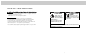
IMPORTANT–Please Read and Follow! A GFI shall be used if required by NFPA-70 (National Electric Code), federal/state/local laws, or local ordinances. • The required use of a GFI is normally related to the location of a receptacle with respect to any significant sources of water or moisture. • Viking Range, LLC will NOT warranty any problems resulting from GFI outlets which are not installed properly or do not meet the requirements below.
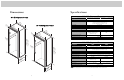
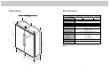
Dimensions Specifications 30” All Refrigerator/Freezer 30” All Refrigerator/Freezer Description Overall width Overall height (from bottom) Overall depth (from rear) 2 (73 9” .7 c m) 3 -1 (8.9 /2” cm ) 36” All Refrigerator/Freezer 30 (76 ” .2 cm ) Maximum amp usage Inlet water requirements 3 ies varare) t en w 3-1 rd rem d ha asusupplie e M ally 75 (88 5” .9 c m) (8.9 /2” cm ) Cutout width Cutout height Cutout depth Electrical requirements 3 (91 6” .
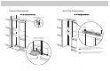
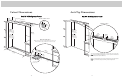
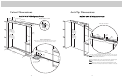
Cutout Dimensions Anti-Tip Dimensions 30” All Refrigerator/Freezer 30” All Refrigerator/Freezer 4” 2 cm) (61.0 See an ti-t Electric Outlet Location ip boa rd inst a llation 6” (15.2 cm) Anti-Tip Location 9” (22.9 cm) 9” (22.9 cm) 79 (201 -3/8” .6 to bo cm) min . 82-7 / .5 cm8” (210 (3.8 c anti- ttom of tip b oard antitip ) min open board . & ing h eigh t 23” (58.4 c m) 8 (204 0-1/2” .6 to bo cm) max 84 (213 -1/16” .5 anti- cm) m tip b ax.
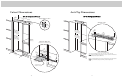
Cutout Dimensions 24” ) .0 cm (61 Anti-Tip Dimensions 36” All Refrigerator/Freezer 36” All Refrigerator/Freezer See an ti-t Electric Outlet Location ip boa rd inst a llation 6” (15.2 cm) Anti-Tip Location 9” (22.9 cm) 9” (22.9 cm) 79 (201 -3/8” .6 to bo cm) min . 82 (210 -7/8” .5 anti- cm) mi tip n anti- ttom of tip b oard open board . & ing h eigh t 29” (73.7 c m) 80-1 (204 84 .6 (213 -1/16” .5 anti- cm) m tip b ax. ope ning oard & h e ig ht ” 1-1/2m) (3.
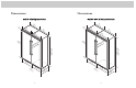
Dimensions Dimensions Dual 30” All Refrigerator/Freezer Dual 30” & 36” All Refrigerator/Freezer 2 2 3 -1 (8.9 /2” cm ) (73 9” .7 c m) 3-1 3 (76 0” .2 c (8.9 /2” cm ) 2 (73 9” .7 c m) m) (73 9” .7 c m) 3 (76 0” .2 c m) 3 (88 5” .9 c m) 3 3 (76 0” .2 c m) 75 -1 (91 6” .5 c m) 75 ies varare) t n w e rd -1 (19 5/1 2.9 6” cm ) ies varare) t en rdw (19 5/1 2.9 6” cm ) rem d ha asusupplie e M ally rem d ha asu pplie Meally su (loc (loc 82 82 (21 -7/8 0.5 ” mincm) .
Dimensions Specifications Dual 36” All Refrigerator/Freezer Dual All Refrigerator/Freezer* Description Overall width Overall height (from bottom) Overall depth (from rear) 3 3 -1 (8.9 /2” cm ) (88 5” .9 c m) 3 (91 6” .5 c m) Cutout width Cutout height Cutout depth Electrical requirements 3 (88 5” .9 c m) 3 (91 6” .
Cutout Dimensions Anti-Tip Dimensions Dual 30” All Refrigerator/Freezer See an ti-tip b oard in stallatio n 24” ) .0 cm (61 Dual 30” All Refrigerator/Freezer Electric outlet location 6” (15.2 cm) Anti-Tip Location 9” (22.9 9” (22.9 cm) cm) 79 (201 -3/8” .6 cm )m to 82 (210 -7/8” .5 anti- cm) mi tip b n. oa open ing h rd & eigh t bo in. anti- ttom of tip b oard 73-3/ (186.4 8” cm) 23” 8 (204 0-1/2” .6 to bo cm) max 84 (213 -1/16” .5 cm anti) ma t ope ip board x.
Cutout Dimensions Anti-Tip Dimensions Dual 30” & 36” All Refrigerator/Freezer 24” ) .0 cm (61 See an ti-tip b oard in stallatio n Dual 30” & 36” All Refrigerator/Freezer Electric Outlet Location 6” (15.2 cm) Anti-Tip Location 9” (22.9 9” (22.9 cm) cm) 82 (210 -7/8” .5 anti- cm) mi tip b n. oa open ing h rd & eigh t 79 (201 -3/8” .6 to bo cm) min . anti- ttom of tip b oard 73-3 (186.4/8” cm) 29” 8 84 (204 0-1/2” .6 to bo cm) max (213 –1/16” .5 anti- cm) m t a op ip boa x. (73.7 c .
Cutout Dimensions Anti-Tip Dimensions Dual 36” All Refrigerator/Freezer Dual 36” All Refrigerator/Freezer See an ti-tip b oard in stallatio n 24” ) cm (61.0 Electric Outlet Location 6” (15.2 cm) Anti-Tip Location 9” (22.9 9” (22.9 cm) cm) 82 (210 -7/8” .5 anti- cm) mi tip b n. oa open ing h rd & eigh t 79 (201 -3/8” .6 cm )m to 73-3/ (186.4 bo in. anti- ttom of tip b oard 8” cm) 29” 8 (204 0-1/2” .6 to bo cm) max 84 (213 -1/16” .5 cm anti) ma t ope ip board x.
Overlay Dimensions Custom Grille Dimensions 30” Custom Panels 30” Custom Grille 1 ” 3/4cm) (1.9 29 ius ad 36” Custom Panels - (1.2/2” 7c m) (74 1/4” .3 c m) ” 1/2cm) 3” m) 7 (1.2 35 - (89 1/4” .5 c m) 2 (7.6 Reverse dimensions for other end. (14 /32 .10 ” cm ) s 1/ diu (1.2 2” Ra ) 7c ” m m 4 c 1/ (.64 -2 (63 7/3 .10 2” cm ) 0c 26 m) /4” 3-3 m) - (66 3/16 .51 ” cm ) 2c (9.5 /8” 3-5 cm) 1 (1.2/2” 7c m) 75 ) 24 c 3 (1.9/4” (1.9 ” 0c m) 1 (1.2/2” 7c m) 1c (3.
Custom Grille Dimensions Custom Grille Dimensions Dual 30” Custom Grille 36” Custom Grille 3 (1.9/4” 0c m) 4” -3/ ) 2 8 cm 9 4-1 ” 1/2cm) (1.2 3” m) 7 2 (7.6 c 1- cm 1 (10 1/64 .59 ” cm ) s / diu (1.2 2” Ra ) 7c ” m m) 4 1/ 64 c -2 (78 7/3 .34 2” cm ) (9.5 (1.9/4” 0c m) 32 - (81 3/16 .75 ” cm ) 2 /4” 3-3 cm) 3 (1.9/4” 0c m) (9.2 1 (1.2/2” 7c m) 2 (7.9 (1.2 ” 7c m) 3/4” 2-7 ” cm ) 1 (2.5 ” 4c m ) 0c (9.2 54 - (13 27/3 9.3 2” 0c m) 1/2 (1.
Custom Grille Dimensions Custom Grille Dimensions Dual 30” & 36” Custom Grille 4-1 (1 1/6 1 (1.2/2” 7c m) ius ad ”R ) 1.2 4” 7c m) m 4 1/ (.16.42 c (1 2c (7.6 26 (66 3/16 . 2c (1.03 cm) 7c m) (7.3 8” 0c m) 34 -1 (86 1/6 4 0c m) .80 2 (9 .5 ” cm .90 (9 .2 ) 0c 60 (15 27/3 4 2 /4” 3-3 cm) 3 /8” 3-1 cm) 7c m) (7 ” cm ) cm ) 1 (2.5 ” 4c m cm ) ) 66 16927/3 .78 2” /4” 3-3 cm) 2 68 m) /8” 3-1 cm) 69 Note: This part should be located at the center of the grille.
Cabinet Information Cabinet Information Custom panel models, (with 3/4” [1.9 cm], thick panels and custom handles locally supplied), fit flush in 25” (63.5 cm) deep (countertop depth) cabinet openings with no protrusion into room except custom handles Custom panel models can be installed in standard 24” (61.0 cm) deep openings. However, the door faces and top ventilation grille will protrude 3/4” (1.9 cm) into the room. This is ideal for alignment with full overlay cabinet doors.
Custom Side Panel Dimensions Custom Panel General Information Custom finishing options Z-Bracket 1” (2.5 cm) • Panel thickness must not exceed 1” (2.5 cm) on hinge side. Thicker panels will interfere with door swing and clearance. • Door panels should be installed after the refrigerator has been plugged in for at least 24 hours. • All installations must allow for the refrigerator and freezer door to open a minimum of 90˚. • For side wall or corner installation, allow for a standard 3” (7.
Custom Door Panel Installation Custom Door Panel Installation 2 1 x2 Remove handle side cabinet screws and trim with a phillips screwdriver. 4 2-1/16” (5.2 cm) 1-11/16” (4.3 cm) x2 Reinstall handle side door trim and door trim screws. Slide custom wood panel to the hinge side, ensuring “Z” bracket engages the door bracket. 9 2-13/16” (7.1 cm) Bottom-mount 12-1/16” (30.6 cm) All Refrigerator/ Freezer/ Side-by-side 2-1/8” (5.4 cm) Back of panel “Z” bracket Remove bracket.
Custom Grille Installation Custom Grille Installation (cont.) 2 1 Remove air grille center blade. 7 Remove two 1/4” (0.6 cm) screws with a magnetic extended screwdriver at least 8” (20.3 cm) long. 3 8 Install two 1/4” (0.6 cm) screws with a magnetic extended screwdriver at least 8” (20.3 cm) long. Install custom air grille center blade. 4 Pull air grille assembly forward. Remove 2 mounting brackets from the grille air assembly.
General Information General Information Area Requirements Water Supply Requirements A 115 volt, 60-Hz, 15 amp, fused, electrical supply is required. It is required that a separate circuit serving only this appliance be provided. This appliance is equipped with a power supply cord having a 3-prong grounding plug. To minimize possible shock hazard, the cord must be plugged into a mating 3-prong, grounding-type wall receptacle. DO NOT use an extension cord.
Installation General Information 1 2 Tip Over Hazard • Most of the unit’s weight is at the top. Extra care is needed when moving the unit to prevent tipping. Appliance is top heavy and tips easily when not completely installed. Keep doors closed until appliance is completely installed and secured per installation instructions. Use two or more people to move and install the appliance. Failure to do so can result in death or serious injury.
8a 7 12 11 1 Wall 2 2x4 Refrigerator Attach one 2 x 4 to wall stud (refer to dimensions page for exact location). Replace unit top and four side screws. 9 8b Flush water line by running two quarts of water into a bucket. Turn water off Pull supply tubing forward under unit. Note: DO NOT use plastic water lines. 14 13 Wall 2x4 Refrigerator Plug in power cord to verify operation. Note: Make sure power switch and showroom switch are in the “On” position.
Final Installation 17 29 28 Replace top air grille. Verify that drain pan is installed and aligned. Using an 8” magnetic nut driver, replace the two 1/4” screws. Kickplate Installation 18 19 30 1 1 31 2 3 2 Align holes on both ends of louvered panels and insert screws. Using a phillips screwdriver, attach the kickplate to the unit and adjust to desired height. Replace the center grille louver. Open door. The display should flash.
Performance Checklist Verify Operations Control Panels All Refrigerator FREEZER ACTIVATE CONTROLS REF TEMP HIGHER LOWER HIGHER LOWER CF MAX FRZ MAX REF FAST COOL SAB SHOW REFRIGERATOR DOOR OPEN POWER HIGH TEMP FAST COOL MAX REF ALARM OFF DISPLAY OFF REFRIGERATOR DOOR OPEN POWER HIGH TEMP FAST COOL MAX FRZ ALARM OFF DISPLAY OFF All Freezer FREEZER ACTIVATE CONTROLS FRZ TEMP CF MAX FRZ MAX REF FAST COOL SAB SHOW 1. Press “Activate Controls” pad. 2. Verify unit is not in Sabbath Mode.
Service & Registration Only authorized replacement parts may be used in performing service on the appliance. DO NOT repair or replace any part of the appliance unless specifically recommended in the manual. All other servicing should be referred to a qualified technician. Record the following information indicated below. You will need it if service is ever required.