
User manual


Weld Control Selector Guide - Page 28
CONTACTOR OUTPUT CONFIGURATION
Contactor Selection
There are two types of contactor signals that various power supply manufacturers use. A "Closing Contact
or Contactor" and a “115VAC Contactor” signal. Once the power supply contactor is closed, the welding
leads become electrically live and are referred to as being “live” or “hot”.
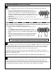
For the Closing Contactor type, the weld control simply touches the two contactor leads together (providing
a continuity signal to the power supply) like a light switch. ALL Cobramatic wire feeders and Weld Controls
are shipped in this conguration (Figure A). Since no voltage is applied to the leads in tis conguration, it
is safe to handle and there is no risk of personal injury from electrocution.
Figure A
For the 115VAC Contactor type, the weld control must send 115VAC into the power supply to close the
contactor. In order to obtain this conguration from a Cobramatic wire feeder or Weld Control, the internal
wiring or each must be modied as shown (Figure B).
Figure B
If a 115VAC signal is required, remove the four screws from both sides of control box, and remove
cover. For Cobramatic open left door. Locate white and black wire on #3 and #4 of terminal strip J6.
Move white wire to #3 and black wire to #4 of terminal strip J5. The unit will now supply 115VAC on
the black (hot) and white (neutral) wires.
WARNING: Disconnect the WC-1 & Cobramatic from all power sources before changing contactor.
WHITE
BLACK
CLOSING
CONTACTS
CONNECTION
COBRAMATIC / WC-1
MAIN BOARD
2
J6
1 43
J5
2
1 43
115 VAC
CONTACTOR
CONNECTION
WHITE
BLACK
COBRAMATIC / WC-1
MAIN BOARD
2
J6
1 43
J5
21 43