
Service manual


22956 Highway 61 Morley, MO 63767 PH: 573-262-3545; FAX: 573-262-3369 www.vikingcives.com
New LD Manual 31 Revision 08
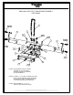
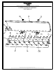
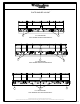
SNO-KING MOLDBOARD / PUSHFRAME ASSEMBLY INSTRUCTIONS:
1. Position the moldboard assembly face down on a flat surface.
2. Remove the factory installed 1” and ¾” fasteners from the left and right torque arm assemblies.
3. Utilizing adequate lifting equipment and proper safety procedures, position the torque tube and A-frame assembly into the
rear moldboard cavity and attach with the 1” x 2 ½” fine thread bolts and flat washers, (a coating of premium grade anti-seize
thread compound is recommended) but do not completely tighten at this time.
4. Rotate the torque tube and A-frame assembly towards the moldboard and attach, but do not completely tighten at this time,
the torque arms to the center moldboard rib adjusting holes with the ¾” x 2 ½” bolts and nuts while positioning the flat
washer on the moldboard side of the ribs.
5. Apply thread sealant onto the 90-degree pipefittings and install into the moldboard reversing cylinders.
6. Attach the correct reversing cylinder hose assemblies as indicated in the parts and service manual for your hydraulic
application. A cushion valve is required on all central hydraulic systems. (Please note memo on page 18)
7. Connect each end of the lift chain assembly to the A-frame lifting lug with the ½” clevis mid link provided.
8. Once the completed plow assembly has been properly installed on the truck it will be necessary to adjust the moldboard to an
angle of attack of 22 – 25 degrees and adequately tighten both the torque tube and torque arm fasteners at that time.