Installation 3 Series Freestanding 30” Electric Self-Clean Range RVER3301 / CRVER3301
Table of Contents Warnings & Important Safety Instructions _______________________________________________3 Dimensions _________________________________________________________________________6 Specifications _______________________________________________________________________7 Clearance Dimensions (Proximity to Cabinets) ___________________________________________8 Clearance Dimensions (Wood/Composite Overlay) ______________________________________9 Electrical Requirements ______________________________
IMPORTANT –Read and Follow! • Before beginning, please read these instructions completely and carefully. Your safety and the safety of others is very important. • DO NOT remove permanently affixed labels, warnings, or plates from product. This may void the warranty. We have provided many important safety messages in this manual and on your appliance. ALWAYS read and obey all safety messages. This is the safety alert symbol. This symbol alerts you to hazards that can kill or hurt you and others.
IMPORTANT–Read and Follow! A GFI shall be used if required by NFPA-70 (National Electric Code), federal/state/local laws, or local ordinances. • The required use of a GFI is normally related to the location of a receptacle with respect to any significant sources of water or moisture. • Viking Range, LLC will NOT warranty any problems resulting from GFI outlets which are not installed properly or do not meet the requirements below.
WARNING WARNING TIPPING HAZARD ELECTRICAL SHOCK HAZARD To reduce the risk of the appliance tipping, it must be secured by a properly installed anti-tip bracket(s). To make sure the bracket has been installed properly, look behind the range with a flashlight to verify proper installation engaged in the rear top left corner of the range or under the range to verify that a floor hook and bracket have been installed.
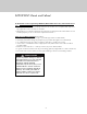
Dimensions RVER/CRVER 29 (75-7/8 .9 ” cm ) 3 (91 5-7 .1 /8” cm ) to min . (94 37 .0 ” cm )m ax . 27-1/8” (68.9 cm) 25” (63.5 cm) 6” (15.2 cm) 29” (73.7 cm) 35-7/8” 25” (63.5 cm) (91.1 cm) min. to 37” (94 cm) max. 19-1/4” 25-3/4” (65.4 cm) (48.9 cm) 45” (114.3 cm) 24” (61.
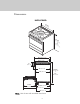
Specifications Electric 30” Range RVER/CRVER Description Overall width 29-7/8” (75.9 cm) Overall height To top of glass frame 35-7/8” (91.1 cm) min. to 37” (94.0 cm) max. Legs adjust 1-1/8” (2.9 cm) Overall depth from rear To end of side panel—25” (63.5 cm) To front of door—25-3/4” (65.4 cm) To front of control panel—27-1/8” (68.9 cm) To end of knobs—29” (73.7 cm) Additions to base height To top of island trim—add 0” (0.0 cm) To top of backguard—add 6” (15.
Clearance Dimensions (Proximity to Cabinets) • This range may be installed directly adjacent to existing 36” (91.4 cm) high base cabinets. CAUTION To prevent possible damage to cabinets and cabinet finishes, use only materials and finishes that will not discolor or delaminate and will withstand temperatures up to 194°F (90°C). Heat and moisture resistant adhesive must be used if the product is to be installed in laminated cabinetry.
Clearance Dimensions (Wood/Composite Overlay) The bottom of a standard hood should be 30” (76.2 cm) min. to 36” (91.4 cm) max. above the countertop. This would typically result in the bottom of the hood being 66” (167.6 cm) to 72” (182.9 cm) above the floor. Refer to the range hood installation instructions for additional information. These dimensions provide for safe and efficient operation of the hood. Wo o d/C o Ov mpo erl sit ay e ” 24 cm) .0 (61 or 66 (16 ”mi 7.6 n. c 72 to m) (18 ”ma 2.9 x.
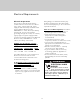
Electrical Requirements Electrical Requirements Viking Range, LLC will NOT warranty any problems resulting from GFI outlets which are not installed properly or do not meet the requirements below. This product is manufactured with the neutral terminal connected to the cabinet. Use a 3-wire, agency approved, power supply kit with closed loop terminals rated per the National Electrical Code, ANSI/NFPA-70 – latest edition (See Rating chart below).
Electrical Requirements Electric access area 6” (15.2 cm) 3-1/2” (8.9 cm) 6” 4-3/8” (15.2 cm) (11.1 cm) 3” (7.
General Information READ AND FOLLOW ALL WARNING AND CAUTION INFORMATION WHEN INSTALLING THIS APPLIANCE. Moving, Handling, and Unpacking Remove and discard all packing materials, including cardboard and tape on the outside and inside of the range. • All openings in the wall behind the appliance and in the floor under the appliance must be sealed. Range – DO NOT discard the anti-tip metal brackets (2) supplied with the range. These are the anti-tip devices and one must be installed with the unit.
Installation CAUTION To avoid risk of personal injury or product damages, DO NOT use the handle or oven door to lift the oven. Remove door before installation to ensure that it is not used to lift the unit. DO NOT lift or carry the door by the handle. Removing the door must be done by your dealer, or a qualified licensed plumber. Door Removal 2 1 Open door completely. Fold latches back until locked in place. Gently close until latches stop door 3 Lift door up and out.
Leg Installation 2 1 1 1 3 2 Legs are packed in styrofoam top pack. Note: Legs should be installed near to where appliance is to be used, as they are not secure for long transit. Note: It is strongly recommended that a pallet or lift jack be used rather than tilting. Raise unit about a foot. Unscrew temporary legs from couplings. 4 3 Lower range gently to keep any undue strain from legs and internal mounting hardware. Screw legs into couplings on all four corners.
Electrical Connection (3-wire) Note: If you have a 4-wire connection, see following section for 4-wire connection instructions. WARNING WARNING ELECTRICAL SHOCK HAZARD ELECTRICAL SHOCK HAZARD To avoid risk of electrical shock, personal injury or death; verify your appliance has been properly grounded in accordance with local codes or in absence of codes, with the National Electrical Code (NEC). ANSI/NFPA-70 – latest edition.
Electrical Connection (3-wire) (cont.) Bare Wire Connection Eyelet Connection 4 1 2 1 1 Attach line #1 (black) and line #2 (red) leads to outside terminal. Attach neutral wire (white) to center terminal on the terminal block. To make a bare wire connection, use holes on the left side of the terminal block. To connect eyelet style wires, use holes on right side of terminal. 5 6 1 1 3 2 Reattach access door.
Electrical Connection (4-wire) WARNING WARNING ELECTRICAL SHOCK HAZARD ELECTRICAL SHOCK HAZARD To avoid risk of electrical shock, personal injury or death; verify your appliance has been properly grounded in accordance with local codes or in absence of codes, with the National Electrical Code (NEC). ANSI/NFPA-70 – latest edition. To avoid risk or electrical shock, personal injury or death; grounding product to the frame of the unit may or may not be permitted through your local codes.
Electrical Connection (4-wire) (cont.) Bare Wire Connection Eyelet Connection 4 1 1 Feed supply cord up through hole in bottom of range back. To make a bare wire connection, use holes on the left side of the terminal block. To connect eyelet style wires, use holes on right side of terminal. 6 5 1 1 2 2 Attach line #1 (black) and line #2 (red) leads to outside terminal. Attach neutral wire (white) to center terminal on terminal block.
Leveling/Adjustments/Alignment 2 1 Measure the four corners in cutout area to verify if flooring is level. For uneven or sloped floors, level unit with metal shims only, as the adjustment required may exceed the thread available in the leg. 4 3 ” 3/8cm) 95 (0. Check that unit is level side to side and front to back. Side trim of the high corner must be 3/8” (0.95 cm) above countertop. Move unit into opening. 6 5 1 1 2 If leveling is required, move unit out of opening.
Leveling/Adjustments/Alignment (cont.) 7 Set the high corner of range so that the top of side trim is 3/8” (0.95 cm) above countertop. Level range to high corner. Anti-tip Device Installation WARNING WARNING TIPPING HAZARD TIPPING HAZARD To reduce the risk of the appliance tipping, it must be secured by a properly installed anti-tip bracket(s).
Wall Mount Anti-tip Installation 2 1 3-5 (9. /8” 2 cm ) ) ) (A .3 cm 1 ( /2” +1 (A ) Measure from floor to bottom of the anit-tip opening located on the back of range. This will be measurement (A). Locate anti-tip bracket on rear wall with the top left corner at measurement (A) plus 1/2” (1.3 cm) from the floor and 3-5/8” (9.2 cm) from where the right side of range (facing range) is to be located. 4 3 Attach bracket with mounting hardware provided.
Floor Mount Anti-tip Installation 1 Dim A from Rear Wall WIthout Standoffs 3-7/8“ (9.8 cm) Dim A from Rear Wall WIth Standoffs 4-5/8” (11.7 cm) A 8- (2011/2 4 .96 ” cm ) Ø 1 (.3 /8” 2c m) Refer to chart for dimension A based on whether or not standoffs are used with the rear trim device. Mark and drill 1/8” (.32 cm) holes where bracket will be located. 2 3 1 1 2 x2 1 2 Remove two screws from back of range. Mount anti-tip bracket hook to floor using screws provided.
Final Installation 2 1 Connect electrical in shaded area. See the “Electrical Requirements” section for more information. Slide range into place. Be sure anti-tip bracket slides into the anit-tip opening. 3 ” 3/8cm) 95 (0. Check that unit is level side to side and front to back. The side trim must be 3/8” (0.95 cm) above countertop. If unit is not level repeat Steps 5-7 of “Leveling/Adjustments/Alignment” section.
Door Replacement 2 1 Open door completely. Fold latches forward until locked in place. Carefully realign door on hinges. Slide in and down.
Final Preparation • All stainless steel body parts should be wiped with hot, soapy water and with a liquid cleaner designed for this material. If buildup occurs, DO NOT use steel wool, abrasive cloths, cleansers, or powders! If it is necessary to scrape stainless steel to remove encrusted materials, soak with hot, wet cloths to loosen the material, then use a wool or nylon scraper.
Service & Registration Only authorized replacement parts may be used in performing service on the appliance. All servicing should be referred to a qualified technician. Contact Viking Range, LLC, 1-888-845-4641, for the nearest service parts distributor in your area or write to: VIKING RANGE, LLC PREFERRED SERVICE 111 Front Street Greenwood, Mississippi 38930 USA Range – The serial number and model number for your appliance can be found by opening the door and looking under the control panel.
Viking Range, LLC 111 Front Street Greenwood, Mississippi 38930 USA (662) 455-1200 For product information, call 1-888-845-4641 or visit our website at vikingrange.