Installation 3 Series Built-In Gas Cooktops
Table of Contents Warnings & Important Safety Instructions _______________________________________________3 Dimensions _________________________________________________________________________6 Specifications _______________________________________________________________________7 Cutout Dimensions __________________________________________________________________8 Cutout Dimensions (Cooktop over Single Electric Oven)__________________________________9 Downdraft Dimensions __________________________________
IMPORTANT– Please Read and Follow • Before beginning, please read these instructions completely and carefully. Your safety and the safety of others is very important. • DO NOT remove permanently affixed labels, warnings, or plates from product. This may void the warranty. We have provided many important safety messages in this manual and on your appliance. ALWAYS read and obey all safety messages. • All local and national codes and ordinances must be observed.
IMPORTANT– Please Read and Follow DANGER WARNING FIRE/EXPLOSION HAZARD CHEMICAL HAZARD If not installed, operated and maintained in accordance with the manufacturer’s instructions, this product could expose you to substances in fuel or from fuel combustion which can cause death or serious illness and which are known to cause cancer, birth defects, or other reproductive harm.
IMPORTANT– Please Read and Follow WARNING ELECTRICAL GROUNDING INSTRUCTIONS The cooktop must be electrically grounded in accordance with local codes or, in the absence of codes, with the ANSI/NFPA No. 70-latest edition. Installation should be made by a licensed electrician. This appliance is equipped with a three-prong grounding plug for your protection against shock hazard and should be plugged directly into a properly grounded receptacle. DO NOT cut or remove the grounding prong from the plug.
Dimensions 30” Gas Cooktop 30 (78-3/4 .1 ” cm ) ” 21 cm) .3 (53 36” Gas Cooktop 36 (93-3/4 .3 ” cm ) ” 21 cm) .3 (53 2-1/2” 4-3/8” (6.4 cm) (11.1 cm) 2-1/2” (6.4 cm) 1-3/4” Front view 6 (4.
Specifications Gas Cooktops Description 30” W. Model 36” W. Model Overall width 30-3/4” (78.1 cm) 36-3/4” (93.3 cm) Overall height from bottom to top of grate 4-3/8” (11.1 cm) Overall depth from rear Cutout width 21” (53.3 cm) 29-1/4” (74.3 cm) min. to 29-7/8” (75.9 cm) max. 35-1/4” (89.5 cm) min. to 35-7/8” (91.1 cm) max. Cutout height 3” (7.6 cm) min. burner box only, 5” (12.7 cm) min. for gas outlet not including regulator Cutout depth 20” (50.8 cm) min. to 20-1/4” (51.4 cm) max.
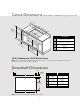
Cutout Dimensions B A C 30” W. Model 36” W. Model A 29-1/4” (74.3 cm) min. to 35-1/4” (89.5 cm) min. to 29-7/8” (75.9 cm) max. 35-7/8” (91.1 cm) max. B 20” (50.8 cm) min. to 20-1/4” (51.4 cm) max. 2-1/2” (6.4 cm) min. C Note: Based on 24” deep cabinet with 3/4” backsplash. If countertop is less than 1-1/2” (3.8 cm) thick, a filler block will have to used for bolt to push against.
Cutout Dimensions (RVGC/CRVGC Cooktop over Single Electric Oven) cm ” i 3 )m .6 (7 n. B 28 C (91”min .4 . cm ) A 36 D (71-1/8 .4 ” cm ) 30” W. Model 14 - (36 1/4” .2 c m) 14-1 (36 /4” .2 c m) (12 .7 5” cm )m ax . A B C D 28 (72-1/2 .4 ” cm ) 29-1/4” (74.3 cm) min. to 29-7/8” (75.9 cm) max. 20” (50.8 cm) min. to 20-1/4” (51.4 cm) max. 14-3/4” (37.4 cm) 14-3/4” (37.4 cm) 30”W. Cooktop over 30”W.
Clearance Dimensions Proximity to Side Cabinet Installation (Proximity to Cabinets) Minimum Clearances from Adjacent Combustible Construction • The cooktop may be installed directly to existing base cabinets. • The cooktop CANNOT be installed directly adjacent to sidewalls, tall cabinets, tall appliances, or other side vertical surfaces above 36” (91.4 cm) high. There must be a minimum of 8” (20.3 cm) side clearance from the cooktop to such combustible surfaces above the 36” (91.4 cm) counter height.
Clearance Dimensions The bottom of a standard hood should be 30” (76.2 cm) min. to 36” (91.4 cm) max. above the countertop. This would typically result in the bottom of the hood being 66” (167.6 cm) to 72” (182.9 cm) above the floor. Refer to the rangehood installation instructions for additional information. These dimensions provide for safe and efficient operation of the hood. (Wood/Composite Overlay) Wo o d/C o Ov mpo erl sit ay e 66 (16 ”mi 7.6 n. c 72 to m) ” (18 ma 2.9 x.
Electrical & Gas Requirements Electrical Requirements Manual shut-off valve: • The installer-supplied valve must be installed in the gas service line ahead of the appliance and regulator in the gas stream and in a position where it can be reached quickly in the event of an emergency. There is no connection necessary beyond plugging the unit into a polarized, grounded, 120 volt, 60 Hz, 15 amp circuit. A minimum of 120VAC is required for proper operation of gas ignition systems. DO NOT use a GFI circuit.
Electrical & Gas Requirements Rigid Connections: • Incoming gas is brought from an intake pipe (not supplied) at the rear of the unit to the pressure regulator; then to the manifold pipe for distribution. The only connection necessary is from the service supply, through the shut-off valve (not supplied), to this intake pipe (not supplied) to the regulator supplied, but not connected through the cooktop. Initial Ignition of Burners All cooktops are tested before leaving the factory.
General Information Electrical Requirement CAUTION Normal grounded household current, 120 volts, 60 Hz, 15 amps, single phase. Electrical installation should comply with national and local codes. BURN HAZARD The use of cabinets for storage above the appliance may result in a potential burn hazard. Combustible items may ignite, metallic items may become hot and cause burns.
Installation 1 2 1 1 1 2 2 2 2 2 Remove the grates and burner caps. Turn the cooktop over and place into countertop opening. Gas & Electrical Connection 1 Note: Refer to “Electrical & Gas Requirements” section for proper installation information.
Bracket Installation 1 2 Cooktop Countertop Cooktop Countertop Screw Eye Bolt Bracket Screw hold down brackets using the #10 x 1/2” sheet metal screw to the burner box. (2 brackets per side) Screw the eye bolt into the self-retaining nut and tighten firmly against bottom of countertop. Final Installation 1 2 2 2 1 1 Bracket 1 1 1 Replace the burner caps and grates. Note: The narrow edge of grate goes toward center of unit.
Final Preparation • New units are cleaned at the factory to remove any visible signs of dirt, oil, grease, etc. remaining from the manufacturing process. Some stainless steel parts may have a plastic protective wrapper which must be peeled off. The cooktop should be washed thoroughly with hot, soapy water and then rinsed and wiped dry to remove these film residues and any installation dust or debris before being used for food preparation.
Service & Registration Only authorized replacement parts may be used in performing service on the appliance. All servicing should be referred to a qualified technician. Contact Viking Range, 1-888-845-4641, for the nearest service parts distributor in your area or write to: VIKING RANGE, LLC PREFERRED SERVICE 111 Front Street Greenwood, Mississippi 38930 USA The serial number and model number for your appliance can be found by looking under the cooktop. Record the following information indicated below.
Viking Range, LLC 111 Front Street Greenwood, Mississippi 38930 USA (662) 455-1200 For product information, call 1-888-845-4641 or visit our website at vikingrange.com in the US or brigade.