Installation 3 Series Freestanding 30” Gas Self-Clean Sealed Burner Range RVGR3302
Table of Contents Warnings & Important Safety Instructions_____________________________________________________ 3 Dimensions __________________________________________________________________________________ 6 Specifications ________________________________________________________________________________7 Clearance Dimensions (Proximity to Cabinets) ________________________________________________8 Clearance Dimensions (Wood/Composite Overlay) ___________________________________________9 Electrical & Gas Re
IMPORTANT– Read and Follow! • Before beginning, please read these instructions completely and carefully. Your safety and the safety of others is very important. • DO NOT remove permanently affixed labels, warnings, or plates from product. This may void the warranty. We have provided many important safety messages in this manual and on your appliance. Always read and obey all safety messages. This is the safety alert symbol. This symbol alerts you to hazards that can kill or hurt you and others.
IMPORTANT– Read and Follow! A GFI shall be used if required by NFPA-70 (National Electric Code), federal/state/local laws, or local ordinances. • The required use of a GFI is normally related to the location of a receptacle with respect to any significant sources of water or moisture. • Viking Range, LLC will NOT warranty any problems resulting from GFI outlets which are not installed properly or do not meet the requirements below.
IMPORTANT– Read and Follow! DANGER DANGER GAS LEAK HAZARD CHEMICAL HAZARD To avoid risk of personal injury or death; leak testing of the appliance must be conducted according to the manufacturer’s instructions. Before placing appliance in operation, always check for gas leaks with soapy water solution. • DO NOT USE AN OPEN FLAME TO CHECK FOR GAS LEAKS. To avoid risk of property damage and/or personal injury or death; this appliance is not too be used as a heating source.
Dimensions RVGR3302 29 (75-7/8 .9 ” cm ) 3 (91 5-7 .1 /8” cm ) to min . (94 37 .0 ” cm )m ax . 27-1/8” (68.9 cm) 25” (63.5 cm) 6” (15.2 cm) 29” (73.7 cm) 35-7/8” 25” (63.5 cm) (91.1 cm) min. to 37” (94 cm) max. 19-1/4” 25-3/4” (65.4 cm) (48.9 cm) 45” (114.3 cm) 24” (61.0 cm) Note: Units shown with standard island trim.
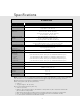
Specifications RVGR3302 Description Overall width 29-7/8” (75.9 cm) Overall height To top of side trim - 35-7/8” (91.1 cm) min. 37” (94.0 cm) max. Legs adjust - 1-1/8” (2.9 cm) Overall depth from rear To front of side panel - 25” (63.5 cm) To front of door - 25-3/4” (65.4 cm) To front of control panel - 27-1/8” (68.9 cm) To end of knobs - 29” (73.7 cm) Additions to Overall Height To top of island trim - add 0” (0.0 cm) To top of backguard - add 6” (15.2 cm) To top of high shelf - add 18-3/16” (46.
Clearance Dimensions • Wall cabinets above the range must be a minimum of 42” (106.7 cm) above the range cooking surface for the full width of the range. This minimum height requirement does not apply if a range hood is installed over the cooking surface. • This range may be installed directly adjacent to existing 36” (91.4 cm) high base cabinets. IMPORTANT: The side trim MUST be 3/8” (.95 cm) above the adjacent base cabinet countertop.
Clearance Dimensions The bottom of a standard hood should be 30” (76.2 cm) min. to 36” (91.4 cm) max. above the countertop. This would typically result in the bottom of the hood being 66” (167.6 cm) to 72” (182.9 cm) above the floor. Refer to the range hood installation instructions for additional information. These dimensions provide for safe and efficient operation of the hood. (Wood/Composite Overlay) Wo o d/C o Ov mpo erl sit ay e ” 24 cm) .0 (61 or 66 (16 ”mi 7.6 n. c 72 to m) (18 ”ma 2.9 x.
Electrical & Gas Requirements Electrical Requirements In Massachusetts: A “T” handle type Check your national and local codes regarding this unit. This range requires 120VAC/60 Hz; 4 ft. (121.9 cm), 3-wire cord with grounded 3-prong plug attached to unit. Must be fused separately from any other circuit. manual valve must be installed in the gas supply line to the appliance. IMPORTANT: Any conversion required must be performed by your dealer or a qualified licensed plumber or gas service company.
Electrical & Gas Requirements Flexible Connections: In Canada: CAN 1-6, 10-88 metal If the unit is to be installed with flexible couplings and/or quick-disconnect fittings, the installer must use a heavy-duty AGA design-certified flexible connector of at least 1/2” (1.3 cm) ID NPT (with suitable strain reliefs) in compliance with ANSI Z21.41 and Z21.69. connectors for gas appliances and CAN 1-6.9 M79 quick disconnect devices for use with gas fuel.
General Information READ AND FOLLOW ALL WARNING AND CAUTION INFORMATION WHEN INSTALLING THIS APPLIANCE. Moving, Handling, and Unpacking Remove and discard all packing materials, including cardboard and tape on the outside and inside of the range. • All openings in the wall behind the appliance and in the floor under the appliance must be sealed. Remove the cardboard top pack containing the burner heads, burner caps, grates, leveling legs and anti-tip bracket from the top of the range.
Installation NOTICE DO NOT use the handle or oven door to lift the oven. Remove door before installation to ensure that it is not used to lift the unit. DO NOT lift or carry the door by the handle. Removing the door must be done by your dealer, a qualified licensed plumber, or certified gas installer. Door Removal 2 1 Open door completely. Fold latches back until locked in place Gently close until latches stop door.
Leg Installation 1 2 1 1 3 2 Legs are packed in the cardboard top pack. Note: Legs should be installed near to where appliance is to be used, as they are not secure for long transit. Note: It is strongly recommended that a pallet or lift jack be used rather than tilting. Raise unit about a foot. Unscrew temporary legs from couplings. 4 3 Lower range gently to keep any undue strain from legs and internal mounting hardware. Screw legs into couplings on all four corners.
4 3 ” 3/8cm) 95 (0. Check that unit is level side to side and front to back. Side trim of the high corner must be 3/8” (0.95 cm) above countertop. Move unit into opening. 6 5 1 1 2 If leveling is required, move unit out of opening. Lift unit and prop on wood blocks. 7 Set the high corner of range so that the top of side trim is 3/8” (0.95 cm) above countertop. Level range to high corner.
Anti-tip Device Installation WARNING WARNING TIPPING HAZARD TIPPING HAZARD • This range can tip. • A child or adult can tip the and be killed. • Failure to install the anti-tip device can result in death or serious burns to children or adults. • If the range is moved, then the anti-tip device must be reengaged. To reduce the risk of the appliance tipping, it must be secured by a properly installed anti-tip bracket(s).
Anti-tip Device Installation (cont.) Floor Mount 1 Dim A from Rear Wall WIthout Standoffs 2“ (5.1 cm) Dim A from Rear Wall WIth Standoffs 2 3/4” (7.0 cm) A 8- (211/2” .6 cm ) Ø 1 (.3 /8” 2c m) Refer to chart for dimension A based on whether or not standoffs are used with the rear trim device . Mark and drill 1/8” (.32 cm) holes where bracket will be located. 2 3 1 1 2 x2 Mount anti-tip bracket hook to floor using screws provided. 1 2 Remove two screws from back of range.
Connecting Gas & Electric DANGER 1 GAS LEAK HAZARD To avoid risk of personal injury or death; leak testing of the appliance must be conducted according to the manufacturer’s instructions. Before placing appliance in operation, always check for gas leaks with soapy water solution. • DO NOT USE AN OPEN FLAME TO CHECK FOR GAS LEAKS. Connect gas and electrical. Before placing appliance in operation, always check for gas leaks.
Door Replacement 2 1 Carefully realign door on hinges. Slide in and down. Open door completely. Fold latches forward until locked in place. 3 Close door.
Final Preparation • All stainless steel body parts should be wiped with hot, soapy water and with a liquid cleaner designed for this material. If buildup occurs, DO NOT use steel wool, abrasive cloths, cleansers, or powders! If it is necessary to scrape stainless steel to remove encrusted materials, soak with hot, wet cloths to loosen the material, then use a wool or nylon scraper.
Service & Registration Only authorized replacement parts may be used in performing service on the appliance. All servicing should be referred to a qualified technician. Contact Viking Range, LLC 1-888-845-4641, for the nearest service parts distributor in your area or write to: VIKING RANGE, LLC PREFERRED SERVICE 111 Front Street Greenwood, Mississippi 38930 USA The model and serial number can be found by either tilting range back or using a mirror to look underneath on the front edge of the bottom base.
Notes ________________________________________________________________________________________________________________________________________________________ ________________________________________________________________________________________________________________________________________________________ ________________________________________________________________________________________________________________________________________________________ ____________________________________________
Notes ________________________________________________________________________________________________________________________________________________________ ________________________________________________________________________________________________________________________________________________________ ________________________________________________________________________________________________________________________________________________________ ____________________________________________
Viking Range, LLC 111 Front Street Greenwood, Mississippi 38930 USA (662) 455-1200 For product information, call 1-888-845-4641 or visit our website at vikingrange.