Installation All Refrigerator / All Freezer VCRB5303 / VCRB5363 / CVCRB5303 / CVCRB5363 VCFB5303 / VCFB5363 /CVCFB5303 / CVCFB5363
Table of Contents Warnings & Important Information ___________________________________________________________________ 2 Tipping Radius and Door Swing ________________________________________________________4 Professional Dimensions & Specifications (30” & 36”) ___________________________________________________ 6 Dimensions & Specifications (30” & 36” with flush mount trim) _____________________________ 8 Cutout Dimensions (30”) _________________________________________________________________ 10 Anti-Tip
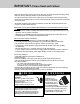
IMPORTANT–Please Read and Follow! • Make sure that incoming voltage is the same as unit rating. An electric rating plate specifying voltage, frequency, wattage, amperage, and phase is attached to the product. • To reduce the risk of fire, electric shock, or injury to persons, installation work and electrical wiring must be done by qualified people in accordance with all applicable codes and standards, including firerated construction.
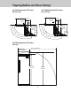
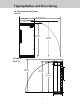
Tipping Radius and Door Swing 36” All Refrigerator/All Freezer Door Swing 30” All Refrigerator/All Freezer Door Swing 17-5/8” (44.8 cm) 14-5/8” (37.1 cm) 12-3/16” (31.0 cm) 10-1/8” (25.7 cm) 110º 120º 30-3/16” (76.7 cm) 24-15/16” (63.3 cm) 26-5/8” (65.1 cm) 28-1/3” (71.9 cm) 90º 32-1/2” (82.6 cm) 110º 120º 30” All Refrigerator/All Freezer Side Tip 112 7/8” (286.7 cm) 30” (76.6 cm) 82 3/4” (210.1 cm) 88 1/16” (223.7 cm) 4 90º 34-3/8” (87.
Tipping Radius and Door Swing 36” All Refrigerator/All Freezer Side Tip 118 7/8” (302.0 cm) 36” (94.4 cm) 82 3/4” (210.1 cm) 90 3/16” (229.1 cm) 30” and 36” Back Tip 86 1/8” (218.8 cm) 85 1/2” (217.2 cm) 82 3/4” (210.1 cm) 24” (61.
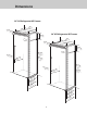
Dimensions 30” All Refrigerator/All Freezer 29” 30” (73.7 c m) (76.2 cm ) 3–19/ 3 (9.1 cm2” ) 36” All Refrigerator/All Freezer 9–5/3 2” (23.3 c m) 35” 36” 3–19/ (88.9 c m) (91.5 c m) 3 (9.1 cm2” )) 9–5/3 (23.3 c2” m) 82–3 (210. /4” 2 cm min. ) to 75–1 (192 5/16” .9 cm ) /2” 26-1 cm) 84–1 / (213. 16” 5 cm max. ) (67.3 82–3 75–1 (192 5/16” .9 cm) (210. /4” 2 cm min. ) to /2” 26-1 cm) 84–1 / (213. 16” 5 cm max. ) (67.3 4” –3/ ) 20 .7 cm (52 ” /16 –3 cm) 2 2 6.
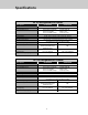
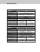
Specifications 30” All Refrigerator/All Freezer Description Overall width Overall height from bottom Overall depth from rear Cutout width Cutout height Cutout depth Electrical requirements Maximum amp usage Inlet water requirements Overall interior dimensions Total capacity Approximate shipping weight VCFB/CVCFB VCRB/CVCRB 30” (76.2 cm) 82-3/4” (210.2 cm) min. to 84-1/16” (213.5 cm) max. To front edge of side trim: 22-3/16” (56.4 cm) To front of top grille: 24” (61.
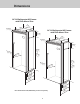
Dimensions 30” All Refrigerator/All Freezer with Flush Mount Trim 29” 30” (73.7 c m) (76.2 c m) 3–19/ 3 (9.1 cm2” ) 36” All Refrigerator/All Freezer with Flush Mount Trim 9–5/3 2 (23.3 c ” m) 35” 36” 3–19/ (88.9 c m) (91.5 c m) 3 (9.1 cm2” ) 9–5/3 (23.3 c2” m) 82–3 (210. /4” 2 cm min. ) to 75–1 (192 5/16” .9 cm ) /2” 26–1cm) 84–1 / (213. 16” 5 cm max. ) (67.3 82–3 75–1 (192 5/16” .9 cm) (210. /4” 2 cm min. ) to /2” 26–1cm) 84–1 / (213. 16” 5 cm max. ) (67.
Specifications 30” All Refrigerator/All Freezer with Flush Mount Trim Description Overall width Overall height from bottom Overall depth from rear Cutout width Cutout height Cutout depth Electrical requirements Maximum amp usage Inlet water requirements Overall interior dimensions Total capacity Approximate shipping weight VCFB/CVCFB Flush Mount VCRB/CVCRB Flush Mount 30” (76.2 cm) 82-3/4” (210.2 cm) min. to 84-1/16” (213.5 cm) max. To front edge of side trim: 23-3/8” (59.
Cutout Dimensions 30” All Refrigerator/All Freezer 24” ) cm (61.0 See An ti-Tip b oard in Electric Outlet Location stallatio n 6” (15.2 cm) 9” (22.9 cm) 9” (22.9 cm) 82 (210 –7/8” .5 anti- cm) mi tip n. open board & ing h eigh t 84 (213 –1/16” .5 anti- cm) m tip b ax. ope ning oard & heig ht 73–3 (186.4/8” cm) Water Line Entry Area Note: Shown for All Freezer Only 30 ” ( Flus 76.2 cm h Mo ) unt on ly 29–5 7–5/ (75. 29–5 2c /8 (75. 29-3 to m) min”. 6 cm /4” ) ma Flus (76 30” x.
Anti-Tip Dimensions 30” All Refrigerator/All Freezer Anti-Tip Location Two 2”x 4” mounting boards 3” (7.6 cm) x 3-1/2” (8.9 cm) 3” ) m (7.6 c 23” (58.4 c m) 3–1/ (8.9 c2” m) 79–3 (201 .6 /8” to bo cm) min . anti- ttom of tip b oard 80 (204 –1/2” .6 to b cm) ma NOTE: If unit is installed deeper than 24” (61.0 cm),then shim behind the mounting board by the difference. x. o anti- ttom of tip b oard Flush Mount Anti-Tip Location One 2”x 4” mounting board 1–1/2” (3.8 cm) x 3-1/2” (8.
Cutout Dimensions 36” All Refrigerator/All Freezer 24” ) cm (61.0 See An ti-Tip b oard in Electric Outlet Location stallatio n 6” (15.2 cm) 9” (22.9 cm) 9” (22.9 cm) 82 (210 –7/8” .5 anti cm) m -ti in open p board . & ing h eigh t 84 (213 –1/16” .5 anti- cm) m tip b ax. ope ning oard & heig ht 73–3 (186.4/8” cm) Water Line Entry Area Note: Shown for All Freezer Only 36 ” ( Flush91.4 cm) Mou nt on ly 35–5 7–5 (90. 35–5 5 cm /8” (90. 35-3 to ) min. 8 cm /4” ) ma Flus (91 36” x.
Anti-Tip Dimensions 36” All Refrigerator/All Freezer Anti-Tip Location Two 2”x 4” mounting boards 3” (7.6 cm) x 3-1/2” (8.9 cm) 3” ) m (7.6 c 29–1/2 (74.9 c ” m) 3–1/ (8.9 c2” m) 79 (201 –3/8” .6 to bo cm) min . anti- ttom of tip b oard 80 (204 –1/2” .6 to bo cm) max NOTE: If unit is installed deeper than 24” (61.0 cm), then shim behind the mounting board by the difference. . anti- ttom of tip b oard Flush Mount Anti-Tip Location One 2”x 4” mounting board 1–1/2” (3.8 cm) x 3–1/2” (8.
Dimensions Dual 30” All Refrigerator/All Freezer* 29” 3–19/ 32” (9.1 cm ) (73.7 c 30” m) (76.2 c 30” (7m6).2 c m) 29” 30” (76.23c0” m (73.7 c m) (76.2 c) m) 9–5/3 (23.3 c2” m) 75–1 (192 5/16” .9 cm ) 82–3 (210.2/4” cm min. ) to 2” 26-1/cm) Dual 30” & 36” All Refrigerator/All Freezer* 84–1 / (213.5 16” cm max. ) (67.3 29” (73.6 c m) 3–19/ 3 (9.1 cm2” ) 35” 30” (88.9 c m) (76.2 c 30” m) 36” (76.2 c m) (91.5 c m) 9–5/3 (23.3 c2” m) ” 3/4 1 (2 ” Bet .
Dimensions Dual 36” All Refrigerator/All Freezer* 35” 3–19/ 32” (9.1 cm ) (88.9 c m) 30” (7 6.2 cm 36” (9)1.5 c m 35” 30” ) (88.9 c m) (76.2 c36” (91m .5) cm) 9–5/3 (23.3 c2” m) 75–1 (192 5/16” .9 cm ) 82–3 (210.2/4” cm min. ) to 2” 26-1/cm) 84–1 / (213.5 16” cm max. ) (67.3 4” –3/ ) 20 .7 cm (52 ” /16 –3 ) 22 .4 cm 1 (2 ” Bet .54 cm wee n U) nits (56 ” 24 cm) .
Dimensions Dual 30” All Refrigerator/All Freezer with Flush Mount Trim* 29” (73.7 cm 3–19/ 32” (9.1 cm ) ) 30” 29” (76.2 cm (73.7 cm ) ) 30” (76.2 cm ) 9–5/3 (23.3 c2” m) 75–1 (192 5/16” .9 cm ) 82–3 (210.2/4” cm min. ) to 2” 26-1/ ) (67.3 cm 84–1 / (213.5 16” cm max. ) Dual 30” & 36” All Refrigerator/All Freezer with Flush Mount Trim* 29” (73.6 c m) 3–19/ 3 (9.1 cm2” ) 1 (2 ” Bet .54 cm wee n U) nits 35” 30” (88.9 c (76.2 c 30” m) m) 36” (76.2 c m) 4” –3/ ) 20 .
Dimensions Dual 36” All Refrigerator/All Freezer with Flush Mount Trim* 35” (88.9 c 3–19/ 3 (9.1 cm2” ) m) 36” 35” (91.5 c (88.9 c m) 36” m) (91.5 cm ) 9–5/3 (23.3 c2” m) 75–1 (192 5/16” .9 cm ) 82–3 (210.2/4” cm min. ) to 2” 26-1/ ) (67.3 cm 84–1 / (213.5 16” cm max. ) 4” –3/ ) 20 .7 cm (52 /8” –3 ) 23 .4 cm 1 (2 ” Bet .54 cm wee n U) nits (59 ” 24 cm) .
Specifications Dual All Refrigerator/All Freezer* Description Overall width Overall height from bottom Overall depth from rear Cutout width Cutout height Cutout depth Electrical requirements Maximum amp usage Inlet water requirements (All Freezer only) (2) 30” Units (1) 36” & (1) 30” Unit (2) 36” Units 60” (152.4 cm) 66” (167.6 cm) 72” (182.9 cm) 82-3/4” (210.2 cm) min. to 84-1/16” (213.5 cm) max. To front edge of side trim: 22-3/16” (56.4 cm) To front of top grille: 24” (61.
Specifications Dual All Refrigerator/All Freezer w/Flush Mount Trim* Description (2) 30” Units Overall width 60” (152.4 cm) 66” (167.6 cm) 72” (182.9 cm) 82-3/4” (210.2 cm) min. to 84-1/16” (213.5 cm) max. To front edge of side trim: 23-3/8” (59.4 cm) To front of top grille: 24” (61.0 cm) To front of handle endcap: 26-1/2” (67.3 cm) 60” (152.4 cm) 66” (167.6 cm) 72” (182.9 cm) 82-7/8” (210.5 cm) min. to 84-1/16” (213.5 cm) max. 24” (61.0 cm) min.
Cutout Dimensions Dual 30” All Refrigerator/All Freezer See An 24” ) .0 cm ti-Tip b (61 oard in Electric Outlet Location stallatio n 6” (15.2 cm) 9” (22.9 9” (22.9 cm) cm) 8 (210 2–7/8” anti- .5 cm) m t openip boardin. ing h & eigh t 73–3 (186.4/8” cm) 84 (213 –1/16 ” . anti- 5 cm) m tip b ax. o oa ng h rd & eigh t peni Water Line Entry Area Note: Cutout opening shown with All Freezer model on left. Reverse water line entry if All Freezer model is on right. 6 7 –5/ (19.
Anti-Tip Dimensions Dual 30” All Refrigerator/All Freezer Anti-Tip Location Two 2”x 4” mounting boards per unit 3” (7.6 cm) x 3–1/2” (8.9 cm) 23” (58.4 c m) 3” ) m (7.6 c 23” (58.4 c m) 79 (201 –3/8” .6 cm )m to 3–1/ (8.9 c2” m) bo in. anti- ttom of tip b oard 80 (204 –1/2” .6 cm )m to Note: If unit is installed deeper than 24” (61.0 cm), then shim behind the anti-tip bracket by the difference. ax.
Cutout Dimensions Dual 30” & 36” All Refrigerator/All Freezer See An 24” ) cm ti-Tip b (61.0 oard in Electric Outlet Location stallatio n 6” (15.2 cm) 9” (22.9 9” (22.9 cm) cm) 82 (210 –7/8” .5 anti- cm) m in tip open board . & ing h eigh t 73–3 (186.4/8” cm) 84 (213 –1/16” .5 anti- cm) m tip b ax. ope ning oard & heig ht Water Line Entry Area Note: Cutout opening shown with All Freezer model on left. Reverse water line entry if All Freezer model is on right. 66 7 –5/ (19.
Anti-Tip Dimensions Dual 30” & 36” All Refrigerator/All Freezer Anti-Tip Location Two 2”x 4” mounting boards per unit 3” (7.6 cm) x 3 1/2” (8.9 cm) 29” (73.7 c 3” ) m m) (7.6 c 79 (201 –3/8” .6 to bo cm) min . 23” (58.4 c m) anti- ttom of tip b oard 3–1/ (8.9 c2” m) 80 (204 –1/2” .6 to cm) m Note: If unit is installed deeper than 24” (61.0 cm), then shim behind the mounting boards by the difference. ax.
Cutout Dimensions Dual 36” All Refrigerator/All Freezer 24” ) .0 cm See An (61 ti-Tip b oard in Electric Outlet Location stallatio n 6” (15.2 cm) 9” (22.9 9” (22.9 cm) cm) 82 (210 –7/8” .5 anti- cm) min tip . open board & ing h eigh t 73–3 (186.4/8” cm) 84 (213 –1/16” .5 anti- cm) m tip b ax. ope ning oard & heig ht Water Line Entry Area Note: Cutout opening shown with All Freezer model on left. Reverse water line entry if All Freezer model is on right. 72 ” (1 Flus 82.
Anti-Tip Dimensions Dual 36” All Refrigerator/All Freezer Anti-Tip Location Two 2”x 4” mounting boards per unit 3” (7.6 cm) x 3–1/2” (8.9 cm) 29” (73.7 c m) 3” ) m (7.6 c m) / .6 8” to bo cm) min . (201 29” (73.7 c 79–3 anti- ttom of tip b oard 3–1/ (8.9 c2” m) 80 (204 –1/2” .6 to bocm) max Note: If unit is installed deeper than 24” (61.0 cm), then shim behind the mounting boards by the difference. .
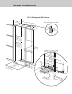
Cabinet Information Professional models fit “semi-flush” in standard 24” (61.0 cm) deep cabinet openings. The door face protrudes 1-3/4” (4.4 cm) from the cabinet face. The handle protrudes an additional 2-1/2” (6.4 cm) into the room. Top View Wall 1–13/16” (4.6 cm) Space if 24” (61.0 cm) standard cabinet depth is used 24” (61.0 cm) Standard cabinet depth 3/4” (1.9 cm) Full end panel Countertop overhang Door 1-3/4” (4.4 cm) Offset Top View Wall 1–13/16” 24” (61.0 cm) Standard cabinet depth (4.
Cabinet Information Professional models fit “semi-flush” in standard 24” (61.0 cm) deep cabinet openings. The door face protrudes 1-3/4” (4.4 cm) from the cabinet face. The handle protrudes an additional 2-1/2” (6.4 cm) into the room. Top View Wall 1–13/16” (4.6 cm) Space if 24” (61.0 cm) standard cabinet depth is used 24” (61.0 cm) Standard cabinet depth 3/4” (1.9 cm) Full end panel Partial overlay cabinet door Door 1-3/4” (4.
Cabinet Information (With Flush Mount Trim) Models with flush mount trim fit flush in standard 24” (61.0 cm) deep cabinet openings with no protrusion into the room except the handle protrudes 2-1/2” (6.4 cm) into the room. Top View Wall 1” (2.5 cm) space if 25” (63.5 cm) cabinet depth is used 25” (63.5 cm) countertop depth 3/4” (1.9 cm) Full end panel Door Flush Top View Wall 1” (2.5 cm) space if 25” (63.5 cm) cabinet depth is used 25” (63.5 cm) 3/4” (1.9 cm) Full end panel Door Flush 28 24” (61.
Cabinet Information (With Flush Mount Trim) Models with flush mount trim fit flush in standard 24” (61.0 cm) deep cabinet openings with no protrusion into the room except the handle protrudes 2-1/2” (6.4 cm) into the room. Top View Overlapping cabinet doors Wall 3/4” (1.9 cm) space if 24” (61.0 cm) standard cabinet depth is used 24-3/4” (62.9 cm) 3/4” (1.9 cm) Full end panel 24” (61.0 cm) Standard cabinet depth Cabinet door Door Flush Top View Flush mount cabinet doors Wall 1” (2.
Custom Side Panel Dimensions 3/16” 3/4” (0.5 cm) Back filler panel ” 16 -7/cm) 2 2 0 . (57 (1.9 cm) End panel 6” m) .2 (15 c 5/32” (0.4 cm) ” /16) 7 m 2 c 2 7.0 (5 (2182-7 0.5 /8 cm ” to ) min 8 (21 4-1 . 3.5 /1 cm 6” )m ax .* (2182-7 0.5 /8 cm ” to ) min 8 (21 4-1 . 3.5 /1 cm 6” )m ax .* 6” m) .2 (15 c 4” -1/ ) 22.5 cm (56 Optional kickplate notch Dimensions determined by cabinets 4” -1/cm) 2 2 .5 (56 * Depending on how high leveling feet are raised, and cabinet enclosure height.
Custom Side Panel Dimensions (With Flush Mount Trim) Z-Bracket 1” (2.5 cm) 1/4” (0.6 cm) 4” -3/ ) 21.2 cm (55 3/4” (1.9 cm) End panel 4” -3/ ) 21.2 cm (55 (2182-7 0.5 /8 cm ” to ) min 8 4 (21 -1 . 3.5 /1 cm 6” )m ax .* (2182-7 0.5 /8 cm ” to ) min 8 (21 4-1 . 3.5 /1 cm 6” )m ax .* ” 24 cm) .0 (61 Optional kickplate notch ” 24 cm) Dimensions determined by cabinets .0 (61 * Depending on how high leveling feet are raised, and cabinet enclosure height.
General Information only this appliance be provided. This appliance is equipped with a power supply cord having a 3-prong grounding plug. To minimize possible shock hazard, the cord must be plugged into a mating 3-prong, grounding-type wall receptacle. Do not use an extension cord. Area Requirements Verify the following: • Unit can fit into residence and can be moved around corners and through doorways. • Floors can support unit’s weight plus food weight (approximately 1200 pounds [540 kg] per unit).
General Information • Do not use the self-piercing feature of a saddle valve. The hole made by the piercing lance is too small for the water flow rate required by the ice maker. Use only 1/4” (6 mm) copper tubing for water line. Do Not install copper tubing in area WARNING • If saddle valve is not used, place a separate shut-off valve in an easily accessible location between water supply and the unit. Do not locate shut-off valve behind the unit.
General Information • Most of the unit’s weight is at the top. Extra care is needed when moving the unit to prevent tipping. Tip Over Hazard Appliance is top heavy and tips easily when not completely installed. Keep doors closed until appliance is completely installed and secured per installation instructions. Use two or more people to move and install appliance. Failure to do so can result in death or serious injury. • Do Not remove protective film until unit is in operating position.
Flush Mount Side Trim Installation Note: If the unit is to be installed flush with the cabinets, the flush mount side trim must be installed first. If not, skip to “installation”. Step 1 - Locate the necessary parts: Two (2) flush mount trim pieces and a hardware kit with twentytwo (22) screws. Step 2 - Remove the side trim on the refrigerator and discard the trim and screws. Step 3 - Align the top of the flush mount side trim with the top of the unit's machine compartment.
Hinge Adjustment 6 5 Front of unit 2 2 1 1 Remove 4 side screws and remove unit top. 3 Loosen the 4 hinge screws. Adjust door. Retighten 4 hinge screws. 7 1 2 Replace unit top. Replace 4 side screws. 8b 8a Wall Wall 2x4 2x4 Refrigerator Refrigerator Attach a single 2 x 4 to wall stud (refer to dimensions page for exact location). If needed, depending on cabinet and depth, attach second 2 x 4 to first 2 x 4.
9 10a 3” Plug in power cord to verify operation. Note: Make sure power switch and showroom switch are in the “On” Position. Place unit within 3” of being flush with cabinets. Note: To avoid cabinet damage, place cardboard between cabinets and unit. When moving unit, do not crimp, kink or crush water supply line. 10b 11 Carefully move unit until semi flush with cabinet (depending on unit). Pull supply tubing forward under unit. Note: DO NOT use plastic water lines.
15 14 Turn on water supply and check for leaks. Lift unit off rollers to desired height and level unit using a 5/16” head wrench. Note: DO NOT use an electric device. Overtightening can cause damage. 17 16 Screw Wall 2x4 Refrigerator Attach positive secure self-tapping bolts to 2 x 4 using a 22” extension. Verify that drain pan is installed and aligned. Kickplate Installation 18 19 1 2 3 2 Using a Phillips screwdriver, attach the kickplate to the unit and adjust to desired height.
Door Stop Adjustment 20 21 1 1 90˚ 110˚ 120˚ 3 2 2 Open refrigerator door so door stop and shoulder screw are accessible. Note: Shoulder screw should be in 110˚ door opening position. Remove shoulder screw and place in 90˚ or 120˚ position. Final Installation 22 23 Replace top air grille. Using an 8”magnetic nut driver, replace the two 1/4” screws. 24 25 Replace the center grille louver. Open door. Display should flash.
26 Press “ACTIVATE CONTROLS” button pad and close door. Note: There is a 6 minute delay before the unit starts.
Performance Checklist Verify cabinet size. Verify electrical supply and water supply (if applicable). Verify drain pan is properly installed and there are no leaks in water connection. Install kickplate. Remove internal packaging and labels and wipe unit down. Install anti-tip device(s) and verify unit is secure. Position unit in cutout, level at desired height, and secure unit. Installer’s information: Plug-in unit and verify operation.
Verify Operations Control Panels All Refrigerator FREEZER ACTIVATE CONTROLS REF TEMP HIGHER LOWER HIGHER LOWER CF MAX FRZ MAX REF FAST COOL SAB SHOW REFRIGERATOR DOOR OPEN POWER HIGH TEMP FAST COOL MAX REF ALARM OFF DISPLAY OFF REFRIGERATOR DOOR OPEN POWER HIGH TEMP FAST COOL MAX FRZ ALARM OFF DISPLAY OFF All Freezer FREEZER ACTIVATE CONTROLS FRZ TEMP CF MAX FRZ MAX REF FAST COOL SAB SHOW 1. Press “Activate Controls” pad. 2. Verify unit is not in Sabbath Mode. If in Sabbath Mode: A.
Service & Registration If service is required, call your authorized service agency. Have the following information readily available. • Model number • Serial number • Date purchased • Name of dealer from whom purchased Clearly describe the problem that you are having.
Viking Range, LLC 111 Front Street Greenwood, Mississippi 38930 USA (662) 455-1200 For product information, call 1-888-(845-4641) or visit our web site at vikingrange.