Use/Installation GUIDE 5 SERIES Rear Downdraft Ventilators VDD5300 VDD5360 VDD5450 VDD5480
MODEL WIDTH BLOWER (purchased separately) VDD5300 VDD5360 VDD5450 VDD5480 VDVI600 Interior or VDVE900 Exterior VDVI600 Interior or VDVE900 Exterior VDVI600 Interior or VDVE900 Exterior, VDVE1200 Exterior VDVI600 Interior or VDVE900 Exterior, VDVE1200 Exterior 30" W. 36" W. 45" W. 48" W. READ AND SAVE THESE INSTRUCTIONS WARNING WARNING TO REDUCE THE RISK OF FIRE, ELECTRIC SHOCK, OR INJURY TO PERSONS, OBSERVE THE FOLLOWING: 1.
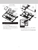
CONTENTS Note: Remove all protective film and packaging before operation. In order to remove all protective film and packaging, raise the ventilator housing and remove the front panel to access the filter area. These parts are included with your downdraft housing: 1 - Parts Bag 4 - Support Legs 1 - Trim Kit 1 - Electrical Panel 2 - Support Brackets PLAN THE DUCTWORK PLANNING HOUSING DO NOT INSTALL WITH COOKING PRODUCTS THAT HAVE A GRIDDLE.
PLAN CABINET CUTOUTS PREPARE THE DOWNDRAFT CAUTION: BEFORE CUTTING HOLE IN CABINET FOR DUCTWORK, check for interference with floor joists, wall studs, electrical wiring, or plumbing. FRONT PANEL COVER CLAMP CHANNEL INSTALLATION CENTER LINE 6 ” 7/ 8 (4-6) HEX NUTS FLUSH HOLE FOR 2” X 19¼” DUCT INSIDE CABINET BACK 26¾” Electrical panel can be mounted remotely. 19¼” 19¼” centered 2” Installations ducting through front panel opening only: 6”* INSIDE CABINET FLOOR 6”* 1.
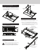
COVER PLATE SLIDE CHANNEL 8" OR 10" ROUND REMOTE DISCHARGE PLATE (Purchase Separatly) UPPER SUPPORT BRACKET COVER PLATES FRONT PANEL Flex Blower shown installed. LOWER CHANNEL Installations using FLEX BLOWER (in remote location) or REMOTE BLOWER only: LONG OR SHORT SUPPORT LEGS 4. Use the REMOTE DISCHARGE PLATE and determine its location on FRONT PANEL. Use a combination of COVER PLATES (3" and/or 6" wide) to close the opening on side(s) of remote discharge plate. HEX SCREW All Installations: 5.
(4) SCREWS Installations where ELECTRICAL PANEL needs to be mounted in a remote location only: 6. Remove (4) HEX NUTS and ELECTRICAL PANEL. 5-ft. extension cables (purchase separately) may be needed to mount electrical panel in a remote location. Do not use more that 2 extension cables. Do not mount electrical panel with vent holes facing down.
CUT COUNTERTOP OPENING 1. Lay out and cut the cooktop cut-out far enough FORWARD so downdraft will fit behind it. 2. Set cooktop in place and slide it as far forward as possible without exposing an gaps. Center and square it with edges of countertop. HEX SCREW (2) SCREWS SUPPORT LEG 3. Extend SUPPORT LEGS and attach to bottom of cabinet with (2) SCREWS through each leg. Tighten HEX SCREWS. COOKTOP UPPER SUPPORT BRACKET Template against back edge of cooktop. 3.
INSTALL DUCTWORK Installations using REMOTE BLOWER only: CAUTION: All electrical wiring should be done by a qualified person(s) in accordance with all applicable codes and standards. CAUTION: Before cutting hole in cabinet for ductwork, check for interference with floor joists, wall studs, electrical wiring, or plumbing. 1. Mount a standard wiring box, with 3-pronged receptacle, within reach of the downdraft's power cord. 1. Cut hole in cabinet as well as holes in wall or floor as necessary. 2.
INSTALL FINISH TRIM INSTALL COOKING APPLIANCE 1. Align the cooking appliance with downdraft and fasten appliance in place following appliance instructions. SCREW CHIMNEY Note: Accurate alignment of cooking appliance and downdraft is necessary to ensure that there is no interference when air vent is raised and lowered. There should be a gap of 1/32" - 1/16" between the back of the cooktop and the front of the downdraft cover.
OPERATION 4-Speed Fan Speed Control 4-Speed Fan Speed Control Press + button to increase fan speed. Press - button to decrease fan speed. After maximum speed is reached, press + button once more to turn off fan. 2-Level Task Light 2-Level Task Light Press once for LOW setting. Press 2x for HIGH setting. Icon will illuminate. Press 3x to turn task light OFF. 30-Hour Filter Clean Reminder 30-Hour Filter Clean Reminder After 30 hours of blower "ON" time, filter clean icon will blink continuously.
USE AND CARE SERVICE INFORMATION Only authorized replacement parts may be used in performing service on the appliance. All servicing should be referred to a qualified technician. WARNING: Always disconnect electric power supply before cleaning and/or servicing unit. Always turn the downdraft blower on before you begin cooking to establish an air flow in the kitchen. Let the blower run for a few minutes to clean the air after you turn the cooktop off. This will keep the whole kitchen cleaner and brighter.
WARRANTY DOWNDRAFT WARRANTY ONE YEAR FULL WARRANTY Downdrafts and all of their component parts, except as detailed below*†, are warranted to be free from defective materials or workmanship in normal residential use for a period of one (1) year from the date of original retail purchase. Viking Range, LLC, warrantor, agrees to repair or replace, at its option, any part which fails or is found to be defective during the warranty period.