Use/Installation GUIDE 5 SERIES Rear Downdraft Ventilators VDD5300 VDD5360 VDD5450 VDD5480
MODEL WIDTH BLOWER (purchased separately) VDD5300 VDD5360 VDD5450 VDD5480 30" W. 36" W. 45" W. 48" W. VDVI600 Interior or VDVE900 Exterior VDVI600 Interior or VDVE900 Exterior VDVI600 Interior or VDVE900 Exterior, VDVE1200 Exterior VDVI600 Interior or VDVE900 Exterior, VDVE1200 Exterior READ AND SAVE THESE INSTRUCTIONS WARNING WARNING TO REDUCE THE RISK OF FIRE, ELECTRIC SHOCK, OR INJURY TO PERSONS, OBSERVE THE FOLLOWING: 1. Use this unit only in the manner intended by the manufacturer.
CONTENTS Note: Remove all protective film and packaging before operation. In order to remove all protective film and packaging, raise the ventilator housing and remove the front panel to access the filter area. These parts are included with your downdraft housing: 1 - Parts Bag 2 - Support Legs 1 - Trim Kit 1 - Electrical Panel 2 - Support Brackets PLAN THE DUCTWORK PLANNING HOUSING DO NOT INSTALL WITH COOKING PRODUCTS THAT HAVE A GRIDDLE.
PLAN CABINET CUTOUTS ! PREPARE THE DOWNDRAFT CAUTION: BEFORE CUTTING HOLE IN CABINET FOR DUCTWORK, check for interference with floor joists, wall studs, electrical wiring, or plumbing. REAR CORNER OF COOKTOP CUT-OUT INSTALLATION CENTER LINE UPPER SUPPORT BRACKETS 5 7/8” FLUSH HOLE FOR 17/8” x 19” DUCT & TRANSITIONS INSIDE CABINET BACK 24¾” DISCHARGE COVERS (REMOVE AND KEEP NUTS) 21” 4” SUPPORT LEGS (KEEP NUT, DISCARD SCREWS) 1. Place the downdraft on its back on a table or flat work surface.
FRONT PANEL COVER COVER PLATE CLAMP CHANNELS 8" OR 10" ROUND REMOTE DISCHARGE PLATE (Purchase Separatly) COVER PLATES 6 HEX NUTS CLAMP CHANNELS FRONT PANEL Electrical panel can be mounted remotely. Installations ducting through front panel opening only: 1. Remove the HEX NUTS on both CLAMP CHANNELS, and detach from the unit. Remove the FRONT PANEL COVER.
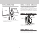
SLIDE CHANNEL Flex Blower shown installed. Installations where ELECTRICAL PANEL needs to be mounted in a remote location only: 5. Remove (4) HEX NUTS and ELECTRICAL PANEL. 5-ft. extension cables (purchase separately) may be needed to mount electrical panel in a remote location. Do not use more that 2 extension cables. Do not mount electrical panel with vent holes facing down. UPPER SUPPORT BRACKET SUPPORT LEG Electrical Panel Dimensions 18-3/16” (46.2 cm) 17-7/16” (44.
Installations using FLEX BLOWER only: CUT COUNTERTOP OPENING 6. Attach BLOWER SUPPORT LEGS with (4) BOLTS provided. 1. Lay out and cut the cooktop cut-out far enough FORWARD so downdraft will fit behind it. ! CAUTION: If flex blower will be mounted remotely: Do not use legs alone for support. It may be necessary to add extra support for the flex blower. Use mounting brackets supplied with the blower. BLOWER SUPPORT LEGS 2.
INSTALL HOUSING INTO CABINET UPPER SUPPORT BRACKET (2) SCREWS 4. Extend UPPER SUPPORT BRACKETS and attached to sides of cabinet with (2) SCREWS through each bracket. FLEX BLOWER 1. Remove cooktop. (4) BOLTS 2. Set housing into cabinet / countertop opening as far back as possible and make sure it is level. 1 HEX NUT SCREWS SUPPORT LEGS (2) SCREWS 1 Installations using FLEX BLOWER only: 5. Loosen (4) BOLTS attaching BLOWER SUPPORT LEGS to FLEX BLOWER.
INSTALL DUCTWORK ! Installations using REMOTE BLOWER only: ! CAUTION: Before cutting hole in cabinet for ductwork, check for interference with floor joists, wall studs, electrical wiring, or plumbing. CAUTION: All electrical wiring should be done by a qualified person(s) in accordance with all applicable codes and standards. 1. Mount a standard wiring box, with 3-pronged receptacle, within reach of the downdraft's power cord. 1. Cut hole in cabinet as well as holes in wall or floor as necessary. 2.
INSTALL FINISH TRIM INSTALL COOKING APPLIANCE 1. Align the cooking appliance with downdraft and fasten appliance in place following appliance instructions. SCREWS CHIMNEY Note: Accurate alignment of cooking appliance and downdraft is necessary to ensure that there is no interference when air vent is raised and lowered. There should be a gap of 1/32" - 1/16" between the back of the cooktop and the front of the downdraft cover.
OPERATION 4-Speed Fan Speed Control 4-Speed Fan Speed Control Press + button to increase fan speed. Press - button to decrease fan speed. After maximum speed is reached, press + button once more to turn off fan. 2-Level Task Light 2-Level Task Light Press once for LOW setting. Press 2x for HIGH setting. Icon will illuminate. Press 3x to turn task light OFF. 30-Hour Filter Clean Reminder 30-Hour Filter Clean Reminder After 30 hours of blower "ON" time, filter clean icon will blink continuously.
USE AND CARE SERVICE INFORMATION Only authorized replacement parts may be used in performing service on the appliance. All servicing should be referred to a qualified technician. WARNING: Always disconnect electric power supply before cleaning and/or servicing unit. Always turn the downdraft blower on before you begin cooking to establish an air flow in the kitchen. Let the blower run for a few minutes to clean the air after you turn the cooktop off. This will keep the whole kitchen cleaner and brighter.
WARRANTY DOWNDRAFT WARRANTY ONE YEAR FULL WARRANTY Downdrafts and all of their component parts, except as detailed below*†, are warranted to be free from defective materials or workmanship in normal residential use for a period of one (1) year from the date of original retail purchase. Viking Range, LLC, warrantor, agrees to repair or replace, at its option, any part which fails or is found to be defective during the warranty period.
Utilisation/Installation GUIDE SÉRIE 5 Hottes arrière encastrées à tirage descendant VDD5300 VDD5360 VDD5450 VDD5480
MODÈLE LARGEUR VENTILATEUR (vendu séparément) VDD5300 VDD5360 VDD5450 VDD5480 76,2 cm (30 po) de largeur 91,4 cm (36 po) de largeur 114,3 cm (45 po) de largeur 121,9 cm (48 po) de largeur VDVI600 intérieur ou VDVE900 extérieur VDVI600 intérieur ou VDVE900 extérieur VDVI600 intérieur ou VDVE900 extérieur, VDVE1200 extérieur VDVI600 intérieur ou VDVE900 extérieur, VDVE1200 extérieur LIRE CES DIRECTIVES ET LES CONSERVER AVERTISSEMENT AVERTISSEMENT OBSERVEZ LES DIRECTIVES CI-DESSOUS AFIN DE RÉDUIRE LES
CONTENU Remarque : Enlevez la pellicule protectrice et les matériaux d'emballage avant l'utilisation. Pour enlever la pellicule protectrice et les matériaux d'emballage, soulevez le boîtier du ventilateur et retirez le panneau avant pour accéder à la zone du filtre.
PLANIFICATION DE LA DÉCOUPE DU COMPTOIR ! PRÉPARATION DE LA HOTTE ENCASTRÉE ATTENTION : AVANT DE DÉCOUPER L’OUVERTURE DES CONDUITS DANS L’ARMOIRE, vérifier que les solives du plancher, les montants des murs, les fils électriques et la plomberie ne présentent aucune nuisance.
COUVERCLE DU PANNEAU AVANT PLAQUE DE SORTIE POUR CONDUITS RONDS DE 20,3 CM (8 PO) OU DE 25,4 CM (10 PO) PLAQUE DE (vendue séparément) RECOUVREMENT PLAQUES DE RECOUVREMENT PROFILÉS DE MONTAGE 6 ÉCROUS HEXAGONAUX PROFILÉS DE MONTAGE PANNEAU AVANT Le boîtier électrique peut être monté à distance. Conduit installé à travers l’ouverture du panneau avant seulement : 1. Retirer les ÉCROUS HEXAGONAUX et les deux PROFILÉS DE MONTAGE et les mettre de côté. Retirer le COUVERCLE DU PANNEAU AVANT.
Installations dans lesquelles le BOÎTIER ÉLECTRIQUE doit être monté à distance seulement : COULISSE 5. Enlever les (4) ÉCROUS HEXAGONAUX et le BOÎTIER ÉLECTRIQUE. Des câbles de rallonge de 1,5 m (5 pi) (vendus séparément) peuvent être nécessaires pour monter le boîtier électrique à distance. Ne pas utiliser plus de deux câbles de rallonge. Ne pas monter le panneau électrique avec les trous d'aération vers le bas. SUPPORT SUPÉRIEUR Ventilateur Flex installé.
DÉCOUPER L’OUVERTURE DU COMPTOIR Installations avec VENTILATEUR FLEX seulement : 6. Fixer les PIEDS DE SUPPORT DU VENTILATEUR à l’aide des (4) BOULONS fournis. ! 1. Tracer et découper l’ouverture de la surface de cuisson suffisamment vers l’AVANT de sorte que la hotte puisse s’encastrer derrière. ATTENTION : Si le ventilateur Flex doit être monté à distance : Ne pas utiliser seulement les pieds comme supports. Il peut être nécessaire d’ajouter d’autres supports au ventilateur.
INSTALLER LE BOÎTIER DANS L’ARMOIRE SUPPORT SUPÉRIEUR (2) VIS 4. Allonger les SUPPORTS SUPÉRIEURS et les fixer sur les côtés de l’armoire avec (2) VIS dans chaque support. VENTILATEUR FLEX (4) BOULONS 1. Enlever la surface de cuisson. 2. Placer le boîtier dans l’armoire et l’ouverture du comptoir aussi loin que possible vers l’arrière et s'assurer qu’il est de niveau. 1 ÉCROU HEXAGONAL VIS PIEDS DE SUPPORTS (2) VIS 1 Installations avec VENTILATEUR FLEX seulement : ÉCROU HEXAGONAL 5.
POSE DES CONDUITS ! Installations avec VENTILATEUR À DISTANCE seulement : ATTENTION : Avant de découper l'ouverture des conduits dans l'armoire, vérifier que les solives du plancher, les montants des murs, les fils électriques et la plomberie ne présentent aucune nuisance. ! ATTENTION : Les travaux d'électricité doivent être effectués par des personnes qualifiées en respectant les codes et les normes en vigueur. 1.
INSTALLATION DE LA BORDURE DE FINITION INSTALLATION DE L’APPAREIL DE CUISSON 1. Aligner l’appareil de cuisson sur la hotte encastrée et le fixer conformément aux instructions qui l’accompagnent. VIS CHEMINÉE Remarque : L’alignement adéquat de l’appareil de cuisson et de la hotte encastrée est nécessaire pour garantir que rien ne nuit à l’ouverture et à la fermeture de la cheminée d’évacuation.
FONCTIONNEMENT Commande de ventilateur à 4 vitesses Commande de ventilateur à 4 vitesses Appuyer sur le bouton + pour augmenter la vitesse du ventilateur. Appuyer sur le bouton - pour diminuer la vitesse du ventilateur. Une fois la vitesse maximale atteinte, appuyer encore une fois sur le bouton + pour arrêter le ventilateur. Éclairage à 2 niveaux Éclairage à 2 niveaux Appuyer une fois pour l’éclairage à FAIBLE intensité. Appuyer 2 fois pour l’éclairage à HAUTE intensité. L’icône s’illumine.
UTILISATION ET ENTRETIEN INFORMATIONS DE SERVICE Lors d’une réparation de l’appareil, n’utiliser que les pièces de rechange autorisées. Tous les travaux doivent être confiés à un technicien qualifié. AVERTISSEMENT : Toujours couper l'alimentation électrique avant de nettoyer ou de réparer l'appareil. Toujours mettre la hotte en marche avant de commencer à cuisiner afin d'établir une circulation d'air dans la cuisine.
GARANTIE GARANTIE DE LA HOTTE ENCASTRÉE GARANTIE LIMITÉE D'UN AN Les hottes encastrées et toutes leurs pièces, à l’exception des articles indiqués ci-dessous*†, sont garanties contre tout défaut de matériau ou de fabrication lors d’une utilisation résidentielle normale pendant une période de un (1) an à compter de la date d’achat originale. Viking Range, LLC, le garant, accepte de réparer ou de remplacer, à son choix, toute pièce s’avérant défectueuse pendant la période de garantie.
Uso/Instalación GUÍA SERIE 5 Ventiladores de tiro descendente posterior VDD5300 VDD5360 VDD5450 VDD5480
MODELO ANCHO VENTILADOR (se compra por separado) VDD5300 VDD5360 VDD5450 VDD5480 30 pulg. (76.2 cm) 36 pulg. (91.4 cm) 45 pulg. (114.3 cm) 48 pulg. (121.
CONTENIDO Nota: Antes de hacerlo funcionar, retire todas las películas protectoras y empaques. Para poder retirar todas las películas protectoras y empaques, levante la cubierta del ventilador y retire el panel delantero para tener acceso al área del filtro.
PLANEE LOS CORTES DEL GABINETE ! PREPARE EL TIRO DESCENDENTE PRECAUCIÓN: ANTES DE HACER LA ABERTURA EN EL GABINETE PARA EL SISTEMA DE CONDUCTOS, revise que no haya interferencia con vigas del piso, montantes de la pared, cableado eléctrico ni tubería. SOPORTES DE APOYO SUPERIORES ESQUINA POSTERIOR DEL CORTE PARA LA ESTUFA LÍNEA CENTRAL DE INSTALACIÓN 57/8 pulg. INTERIOR DE A NIVEL LA PARTE ORIFICIO PARA TRANSICIONES POSTERIOR DEL Y CONDUCTO DE GABINETE 17/8 pulg. x 19 pulg. 24¾ pulg.
PLACA DE DESCARGA REMOTA REDONDA DE 8 PULG. (20.3 CM) PLACA DE O DE 10 PULG. (25.4 CM) CUBIERTA (se compra por separado) PLACAS DE CUBIERTA CUBIERTA DEL PANEL FRONTAL CANALES DE FIJACIÓN 6 TUERCAS HEXAGONALES CANALES DE FIJACIÓN PANEL FRONTAL El panel eléctrico se puede montar de forma remota. Instalaciones con conductos a través de la abertura del panel frontal solamente: CANAL INFERIOR 1. Retire las TUERCAS HEXAGONALES y los dos CANALES DE FIJACIÓN y pongalos a un lado.
Instalaciones en las que el PANEL ELÉCTRICO debe montarse en una ubicación remota solamente: CANAL DE DESLIZAMIENTO 5. Retire las cuatro (4) TUERCAS HEXAGONALES y el PANEL ELÉCTRICO. Es posible que sean necesarios cables de extensión de 5 pies (1.5 m) (se compran por separado) para montar el panel eléctrico en una ubicación remota. No utilice más de dos cables de extensión. No monte el panel eléctrico con orificios de ventilación hacia abajo.
HAGA LA ABERTURA DE LA SUPERFICIE DEL GABINETE Instalaciones que usan el VENTILADOR FLEXIBLE solamente: 6. Fije las PATAS DE APOYO DEL VENTILADOR con los cuatro (4) TORNILLOS suministrados. ! 1. Trace y haga el corte para la estufa lo suficientemente HACIA DELANTE como para que el tiro descendente quepa detrás de la estufa. PRECAUCIÓN: Si el ventilador flexible se va a montar de forma remota: No utilice las patas por sí solas como apoyo.
INSTALE LA CUBIERTA EN EL GABINETE SOPORTE DE APOYO SUPERIOR (2) TORNILLOS 4. Extienda los SOPORTES DE APOYO SUPERIORES y fíjelos a los lados del gabinete con dos (2) TORNILLOS en cada soporte. VENTILADOR FLEXIBLE (4) TORNILLOS 1. Quite la estufa. 2. Fije la cubierta en el gabinete o la abertura de la superficie tan atrás como sea posible y asegúrese de que esté nivelada. 1 TUERCA HEXAGONAL TORNILLOS PATAS DE APOYO (2) TORNILLOS 1 Instalaciones que usan el VENTILADOR FLEXIBLE solamente: 5.
INSTALE EL SISTEMA DE CONDUCTOS Instalaciones con el VENTILADOR REMOTO solamente: ! PRECAUCIÓN: Antes de hacer la abertura en el gabinete para el sistema de conductos, revise que no haya interferencia con vigas del piso, montantes de la pared, cableado eléctrico ni tubería. PRECAUCIÓN: Una o más personas calificadas deben realizar el trabajo de cableado eléctrico, de acuerdo con todos los códigos y las normas correspondientes: 1.
INSTALE LA MOLDURA DE ACABADO INSTALE EL ELECTRODOMÉSTICO DE COCINA TORNILLOS CHIMENEA 1. Alinee el electrodoméstico con el tiro descendente y fije el electrodoméstico en su lugar siguiendo las instrucciones del fabricante. MOLDURA DE ACABADO Nota: Es necesario alinear exactamente el electrodoméstico y el tiro descendente para asegurarse de que no haya interferencia cuando el sistema de ventilación se eleve o baje. Debe haber una separación de 1/32 a 1/16 pulg. (0.8 a 1.
FUNCIONAMIENTO Control del ventilador de 4 velocidades Control del ventilador de 4 velocidades Presione el botón + para aumentar la velocidad del ventilador. Presione el botón - para reducir la velocidad del ventilador. Una vez que se alcance la velocidad máxima, presione el botón + una vez más para apagar el ventilador. Luz de tarea de 2 niveles Luz de tarea de 2 niveles Presione una vez para el ajuste BAJO. Presione dos veces para el ajuste ALTO. El icono se iluminará.
USO Y CUIDADO INFORMACIÓN DEL SERVICIO Solamente se pueden usar piezas de repuesto autorizadas para dar mantenimiento al electrodoméstico. Todo mantenimiento se debe remitir a un técnico calificado. ADVERTENCIA: Siempre desconecte el suministro eléctrico antes de limpiar o dar servicio a la unidad. Siempre encienda el ventilador del tiro descendente antes de comenzar a cocinar para establecer un flujo de aire en la cocina.
GARANTÍA GARANTÍA DEL TIRO DESCENDENTE GARANTÍA COMPLETA DE UN AÑO Los tiros descendentes y todas sus piezas componentes, excepto como se detalla a continuación*†, están garantizados como libres de defectos en materiales o mano de obra en uso residencial normal, durante un periodo de uno (1) año a partir de la fecha de la compra minorista original. Viking Range, LLC, el garante, acepta reparar o reemplazar, a su opción, cualquier pieza que falle o que se encuentre defectuosa durante el periodo de garantía.