
Use and Installation Guide


4
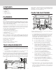
PLAN THE WIRING
1. This downdraft blower using the Flex Blower (purchase
separately) draws 3.0 Amps and requires a 120 VAC, 60 Hz
circuit. If using a remote blower (purchase separately), the
system draws 6.0 Amps (max.) and requires a 120 VAC,
60 Hz circuit.
2. The unit has a 30 in. long power cord with a 3-pronged plug.
Plan to provide a grounded outlet in a location which will
allow the unit’s power cord to reach.
3. Install electrical box according to local codes.
4. The length of cable from the electrical box to the downdraft
is 20 in.
5. The length of blower (sold separately) cable to the electrical
box is 5 ft.
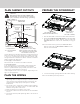
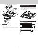
PREPARE THE DOWNDRAFT
1. Place the downdraft on its back on a table or at work surface.
2.
Detach the UPPER SUPPORT BRACKETS from the downdraft
by cutting off the tie wraps. Remove and set aside both
SUPPORT LEGS from sides of the downdraft (one leg per
side).
Note: Discard the retaining screws, but KEEP THE NUTS.
Remove the bundle of 3 DISCHAGE COVERS from the
bottom of the downdraft.
DISCHARGE COVERS
(REMOVE AND KEEP NUTS)
UPPER SUPPORT
BRACKETS
SUPPORT LEGS
(KEEP NUT,
DISCARD SCREWS)
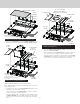
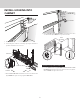
PLAN CABINET CUTOUTS
!
CAUTION:
BEFORE CUTTING HOLE IN CABINET FOR
DUCTWORK, check for interference with oor
joists, wall studs, electrical wiring, or plumbing.
Use the dimensions in the above illustration to help plan how and
where to provide duct access through your cabinet. Generally,
1-7/8" x 19" rectangular duct will be used through left, right,
through cabinet oor and back of cabinet - while 8" round duct
will be used through cabinet oor.
For left, right, or rear exhaust:
Allow at least 18" for transition and elbow or blower.
For left/right exhaust:
A 30" deep cabinet is recommended to align properly with
ex blower. Flex blower can be mounted to rear cabinet
wall or to a platform/frame (not provided) on the base of the
cabinet oor. (See ex blower instructions).
Cabinet depths of 24" to 30" are required - depending on the
type of cooking appliance.
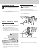
INSTALLATION
CENTER LINE
HOLE FOR
1
7
/
8
” x 19”
DUCT &
TRANSITIONS
INSIDE
CABINET BACK
INSIDE
CABINET FLOOR
21”
centered
4”
21”
REAR CORNER OF
COOKTOP CUT-OUT
24¾”
FLUSH
5 ”
/
8
7
4”
HOLE FOR 8” or
10” ROUND DUCT
(*Adjustable 6” Left and 6” Right)
(When using Remote Discharge Plate -
Hole is adjustable 6” Left and 6” Right
from Installation Center Line.
)
1½” **
6”*
6”*
** Using Flex Blower,
1½” Left from Installation
Center Line
3. Cover the discharge openings that won’t be used for ducting.
Note:
Use the NUTS previously removed.