
Use and Installation Guide


6
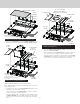
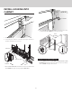
All Installations:
4. Slide UPPER SUPPORT BRACKETS into SLIDE CHANNEL at
top left and right of unit.
Attach previously removed SUPPORT LEGS to downdraft
using one nut for each leg
. Do not tighten nut completely
at this time
.
SLIDE
CHANNEL
SUPPORT
LEG
UPPER
SUPPORT
BRACKET
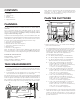
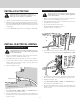
Installations where ELECTRICAL PANEL needs to be
mounted in a remote location only:
5. Remove (4) HEX NUTS and ELECTRICAL PANEL. 5-ft.
extension cables (purchase separately) may be needed to
mount electrical panel in a remote location. Do not use more
that 2 extension cables. Do not mount electrical panel with
vent holes facing down.
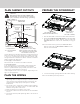
18-3/16” (46.2 cm)
17-7/16” (44.3 cm) Slot Center
4-1/2”
(11.4 cm)
Slot Center
6-1/4”
(15.9 cm)
16-1/4” (15.9 cm)
6-5/8”
(16.8 cm)
Electrical Panel Dimensions
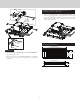
Flex Blower
shown
installed.