Installation Guide ® Viking Range, LLC 111 Front Street Greenwood, Mississippi 38930 USA (662) 455-1200 For product information, call 1-888-(845-4641) or visit vikingrange.
Table of Contents IMPORTANT– Warnings & Important Safety Instructions _______________________________________________3 • Before beginning, please read these instructions completely and carefully. Your safety and the safety of others is very important. • DO NOT remove permanently affixed labels, warnings, or plates from product. This may void the warranty. We have provided many important safety messages in this manual and on your appliance. ALWAYS read and obey all safety messages.
IMPORTANT– Read and Follow! A GFI shall be used if required by NFPA-70 (National Electric Code), federal/state/local laws, or local ordinances. • The required use of a GFI is normally related to the location of a receptacle with respect to any significant sources of water or moisture. • Viking Range, LLC will NOT warranty any problems resulting from GFI outlets which are not installed properly or do not meet the requirements below.
Dimensions Dimensions 36” and 48” W. Ranges 36” and 48” W. Ranges 30” (76.2 cm) 27-3/4 (70.5 cm) 47 (1 -7/ 21 35 8 .6 ” cm ) 2-1/4” (5.7 cm) 1” (2.5 cm) (91-7/8 .1 ” cm ) 8” (20.3 cm) 35-15/16” (91.3 cm) min. to 37-9/16” (95.4 cm) max. 3 5 (91 -15 .3 /16 cm ” )m 3 to in. (95 7-9 .4 /16 cm ” )m ax . 25-1/4” (64.1 cm) 19-3/8” 26-15/16” (49.2 cm) (68.4 cm) 46-5/16” (117.6 cm) Note: Unit shown with standard island trim.
Specifications Specifications Dual Fuel 36” and 48” W. Ranges Gas 36” and 48” W. Ranges Description 36” W. Models 48” W. Models Description 36” W. Models 48” W. Models Overall width 35-7/8” (91.1 cm) 47-7/8” (121.6 cm) Overall width 35-7/8” (91.1 cm) 47-7/8” (121.6 cm) Overall height To top of side trim – 35-15/16” (91.3 cm) min. 37-9/16” (95.4 cm) max. Legs adjust – 1-5/8” (4.1 cm) Overall height To top of side trim – 35-15/16” (91.3 cm) min. 37-9/16” (95.4 cm) max.
Clearance Dimensions Clearance Dimensions (Proximity to Cabinets) • Wall cabinets above the range must be a minimum of 58” (147.3 cm) above the range cooking surface for the full width of the range. This minimum height requirement does not apply if a range hood is installed over the cooking surface. • This range may be installed directly adjacent to existing 36” (91.4 cm) high base cabinets. IMPORTANT: The side panel MUST be 3/8” (.95 cm) above the adjacent base cabinet countertop.
Electrical & Gas Requirements Electrical Requirements - Gas Ranges Gas Connection Check your national and local codes regarding this unit. This range requires 120VAC/60 Hz; 4 ft. (121.9 cm), 3-wire cord with grounded 3-prong plug attached to unit. See “Electrical Connection” section for grounding instructions. Must be fused seperately from any other circuit. This range has a 3/4" (1.9 cm) ID NPT Sch40) inlet connection.
General Information Installation NOTICE READ AND FOLLOW ALL WARNING AND CAUTION INFORMATION WHEN INSTALLING THIS APPLIANCE. Moving, Handling, and Unpacking Remove and discard all packing materials, including cardboard and tape on the outside and inside of the range. • All openings in the wall behind the appliance and in the floor under the appliance must be sealed. Remove the burner grates, burner heads, and bases from the cardboard top packaging.
Installation Installation Leg Installation Electrical Connection (3-wire) - Dual Fuel Ranges Note: If you have a 4-wire connection, see following section for 4-wire connection instructions. 2 1 WARNING WARNING Electrical shock hazard. Electrical shock hazard. 1 1 3 2 Note: It is strongly recommended that a pallet or lift jack be used rather than tilting. Raise unit about a foot. Unscrew shipping bolts from couplings on all four corners. Legs are packed in cardboard top pack.
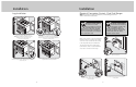
Installation Installation Electrical Connection (3-wire) Dual Fuel Ranges (cont.) Electrical Connection (4-wire) Dual Fuel Ranges 5 4 1 Push supply cord toward terminal block to relieve strain, reattach supply cord strain relief bracket over supply cord. Attach line #1 (red) and line #2 (black) leads to outside terminals. Attach neutral wire (white) to center terminal on the terminal block. 2 1 Remove supply cord strain relief bracket and three supply cord mounting screws on the terminal block.
Installation Installation Electrical Connection (4-wire) (cont.) Leveling/Adjustments/Alignment (con’t) 7 1 4 3 8 ” 3/8cm) 9 (0. Check that unit is level side to side and front to back. Side trim of the lowest corner must be 3/8” (0.95 cm) above countertop. Move unit into opening. Reattach access door. Push supply cord toward terminal block to relieve strain, reattach supply cord strain relief bracket over supply cord.
Installation Installation Anti-tip Device Installation (Wall Mount) Anti-tip Device Installation (Floor Mount) 1 WARNING 1 2 1 TIPPING HAZARD To reduce the risk of property damage or personal injury; install anti-tipping device provided in accordance with the installation instructions in this document. Device must be engaged properly to prevent product from tipping over. 2 1 21 12 (73. -7 83 c /8 m) ” Me as ure me nt Range VGR “X” VDR “X” Width Dimension Di mens ion 36” 24-5/8” (62.
Installation Installation Standoff Spacer Removal Door Replacement DANGER 1 2 FIRE HAZARD Backguards come standard with standoff spacers which provide a barrier between back of range and rear wall. These must be in place for adequate ventilation. Standoff spacers can only be removed if range is installed against a Non-Combustible wall. 1 1 2 Final Installation Reattach door to range. 1a 1 Open door completely. Fold latches forward until locked in place. 3 Slide range into place.
Final Preparation • All stainless steel body parts should be wiped with hot, soapy water and with a liquid cleaner designed for this material. If buildup occurs, DO NOT use steel wool, abrasive cloths, cleansers, or powders! If it is necessary to scrape stainless steel Service & Registration to remove encrusted materials, soak with hot, wet cloths to loosen the material, then use a wooden or nylon scraper.