Installation GUIDE Professional Freestanding Open Burner Gas Ranges VGIC5302 VGIC5362 1
Table of Contents Warnings & Important Safety Instructions ..................................................................................................................................................................3 Dimensions .............................................................................................................................................................................................................................4 Specifications ........................................
Important - Read and Follow! Before beginning, please read these instructions completely and carefully. •DO NOT remove permanently affixed labels, warnings, or plates from product. This may void the warranty. •All local and national codes and ordinances must be observed. Installation must conform with local codes or in the absence of codes, the National Fuel Gas Code ANSI Z223.1 INFPA54.
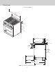
Dimensions 30” AND 36” W. RANGES 35 (91 -7/8 .1 c ” m) 29 (75 -7/8 .9 c ” m) 1” ( 2.5 cm ) (9135-7 .1 c /8” m) to min. (94 37 .0 c ” m) ma x. 28-1/16” (71.2 cm) 1-5/8” (4.1 cm) 26-7/16” (67.2 cm) 1” (2.5 cm) 8-1/8” (20.6 cm) 35-7/8” (91.1 cm) min. to 37” (94.0 cm) max. 19-3/8” 25-3/4” (65.4 cm) (49.2 cm) 45-1/8” (114.6 cm) 24-5/16” (61.
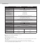
Specifications Description 30” W. (76 cm) Wide 36” W. (91 cm) Wide Overall width 29-7/8” (75.9 cm) 35-7/8” (91.1) Overall height from bottom To top of side panl Leg adjustment Overall depth from rear To end of side panel To front of door To end of landing ledge To end of door handle Additions to Base Height Gas requirements Electrical equirements Maximum amp usage 35-7/8” (91.1 cm) min to 37” (94.0 cm) max 1-1/8” (2.9 cm) 24-5/16” (61.8 cm) 25-3/4” (65.4 cm) 28-1/16” (71.2 cm) 28-11/16” (72.
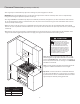
Clearance Dimensions (proximity to cabinets) •This range may be installed directly adjacent to existing 36” (91.4 cm) high base cabinets. IMPORTANT: The side trim MUST be 3/8” (.95 cm) above the adjacent base cabinet countertop. This can be accomplished by raising the unit using the adjustment spindles on the legs. •The range CANNOT be installed directly adjacent to sidewalls, tall cabinets, tall appliances, or other side vertical surfaces above 36” (91.4 cm) high. There must be a minimum of 6” (15.
Clearance Dimensions (wood/composite overlay) Wo od /Co Ov mpos erla ite y Wall Installation ” 24 m) 66 (16 ”min 7.6 . cm 72 to ) ” (18 ma 2.9 x. cm ) .0 c (61 or ” 27 m) .6 c (38 * 30 (76”min .2 c . m 36 to ) ” m (91 ax .4 c . m) Wo od /Co Ov mpos erla ite y 66 (16 ”min 7.6 . cm 72 to ) ” m (18 a 2.9 x. cm ) ” 30 m) .2 c (76 6” ) m 2c . 5 (1 30 (76”min .2 c . m 36 to ) ” (91 max .4 c . m) *Note: Minimum clearance for back wall is 3/4” (1.
Electrical / Gas Requirements WARNING Electrical Requirements Check your national and local codes regarding this unit. This range requires 120VAC/60 Hz; 4 ft. (121.9 cm), 3-wire cord with grounded 3-prong plug attached to unit. See “Electrical Connection” section for grounding instructions. Must be fused seperately from any other circuit.
General Information READ AND FOLLOW ALL WARNING AND CAUTION INFORMATION WHEN INSTALLING THIS APPLIANCE. •All openings in the wall behind the appliance and in the floor under the appliance must be sealed. •Do not obstruct the flow of combustion and ventilation air. CAUTION CAUTION Avoid any damage to oven vents. The vents need to be unobstructed and open to provide proper airflow for optimal oven performance. The cooling fan should be operating when the unit is in operation.
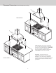
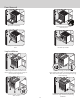
Door Removal 1 step 2 Open door completely. Fold latches backward until locked in place. 3 4 Slowly close until latches stop door. Lift door up and out. Leg Installation 2 1 1 1 3 2 Legs are packed in styrofoam top pack. Note: Legs should be installed near to where appliance is to be used, as they are not secure for long transit. Note: It is strongly recommended that a pallet or lift jack be used rather than tilting. Raise unit about a foot. Unscrew temporary legs from couplings.
Leveling / Adjustments / Alignments 3 2 1 Measure the four corners in cutout area to verify if flooring is level. 4 Move unit into opening. For uneven or sloped floors, level unit with metal shims only, as the adjustment required may exceed the thread available in the leg. 5 6 1 1 2 ” 3/8 m) c 95 (0. Check that unit is level side to side and front to back. Side trim of the high corner must be 3/8” (0.95 cm) above countertop. If leveling is required, move unit out of opening.
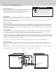
Anti-tip Device Installation - Wall Mount WARNING TIPPING HAZARD To reduce the risk of property damage or personal injury; install anti-tipping at least one device provided in accordance with the installation instructions in this document. Device must be engaged properly to prevent product from tipping over. 1 2 B Me as ure me nt ( 30” 20-3/4” (52.7 cm) 36” 22-3/4” (57.8 cm) B (A) nt mecm) e r asu (.16.
Anti-tip Device Installation - Floor Mount 1 21 (63. --11//22 48 c ””* m) 821 1/2” .6 c m) Ø1 (.3 /8” 2c m) Locate anti-tip bracket hook on the floor 8-1/2” (21.6 cm) from side cabinet and 2-1/2” (6.4 cm) from rear wall when using an island trim or high shelf. *If using an 8” (20.3 cm) backguard with spacers, add 3/4” (1.9 cm) to the 2-1/2” (6.4 cm) for a total of 3-1/4” (8.3 cm). Mark and drill 1/8” (.32 cm) holes where bracket will be located.
Final Installation 1 3 2 ” 3/8cm) Slide range into place. Be sure wall anti-tip bracket slides into the anti-tip opening or floor anti-tip hook and bracket are engaged (depending on the one used) Burner caps and burner bowls are packed in styrofoam top pack with the grates. Place burner bowl in grate support and burner cap on top of burner. Place burner grate over burner cap and on top of grate support. 95 (0. Check that unit is level side to side and front to back. The side trim must be 3/8” (0.
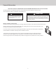
Performance Checklist 1-1/2” A qualified installer should carry out the following checks: Check top burner ignition. See drawing for proper flame height on HI. The low flame should light at every port. (3.8 cm) Check oven bake function—bake burner on full power. 3/8” Check Convection bake function—bake and broil burners the same with the convection fan on. (0.95 cm) Check convection broil function—broil burner at full power with convection fan on.
Viking Range, LLC 111 Front Street Greenwood, Mississippi 38930 662-4551200 For more product information, call 1-888-845-4641 or visit our website at www.vikingrange.