Installation Professional Built-In Electric Single and Double Ovens VSOE130 / VSOE527 / VSOE530 VDOE130 / VDOE527 / VDOE530 Professional Built-In Electric Single and Double French Door Ovens VSOF7301 / VDOF7301
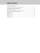
Table of Contents Warnings & Important Safety Instructions _________________________________________________3 Dimensions-Professional Single _________________________________________________________6 Specifications & Electrical Requirements-Professional Single __________________________________8 Cutout Dimensions-Professional Single Built-In _____________________________________________9 Cutout Dimensions-Professional Single Undercounter ______________________________________10 Dimensions-Professional Doubl
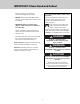
IMPORTANT–Please Read and Follow! • Before beginning, please read these instructions completely and carefully. Your safety and the safety of others is very important. We have provided many important safety messages in this manual and on your appliance. Always read and obey all safety messages. • DO NOT remove permanently affixed labels, warnings, or plates from product. This may void the warranty. • DO NOT install two or more wall ovens single or double side-by-side or stacked on top of the other.
IMPORTANT– Read and Follow! A GFI shall be used if required by NFPA-70 (National Electric Code), federal/state/local laws, or local ordinances. • The required use of a GFI is normally related to the location of a receptacle with respect to any significant sources of water or moisture. • Viking Range, LLC will NOT warranty any problems resulting from GFI outlets which are not installed properly or do not meet the requirements below.
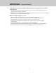
IMPORTANT– Read and Follow! WARNING DANGER To prevent possible damage to cabinets and cabinet finishes, use only materials and finishes that will not discolor or delaminate and will withstand temperatures up to 194°F (90°C). Heat resistant adhesive must be used if the product is to be installed in laminated cabinetry. Check with your builder or cabinet supplier to make sure that the materials meet these requirements.
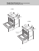
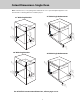
Single Oven Dimensions (Select / Premiere Models) (For cutout dimensions refer to pages 9 and 10) 27” Wide /4” 25–43cm) 7– (65. (183/8” .7 c m) 26 (6 –1 7.3 /2” cm ) 5- (141/2” .0 c m) ” 2 / ) 1 8 6 cm . (21 30” Wide 29 (74-1/ .9 2” cm ) /4” 25–43cm) 7- (183/8” .7 c m) (65. 29 (74–1/2 2” 1/m ) – 2 c 2 2 .9 . (57 5- ” (141/2” .0 c m) cm ) 46”cm) /2” 8-16 cm) .8 116 ( . (21 Rating Label Location 29 (74-1/ .9 2” cm ) ” 1/2 ) 22.–2 cm (57 46”cm) 6.
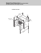
Single Oven Dimensions (French Door Model) (For cutout diminesions refer to pages 9 and 10) 30” Wide French Door /4” –3 ) 255.4 cm (6 8” -7/ ) 13.2z cm (35 Rating Label Location 7 (18-3/8 .7 ” cm ) 29 (74–1/2 .9 ” cm ) 5 (14-1/2 .0 ” cm 2” ) ) / 1 8-.6 cm (21 29 (74-1/2 .9 ” cm ) 8” -5/ ) 390.
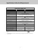
Specifications & Electrical Requirements Professional Single Oven Description Overall Width French Door - Full Door Swing Width 27” Wide 30” Wide 26-1/2” (67.3 cm) 29-1/2” (74.9 cm) N/A 130o 50-5/8” (128.6 cm) Overall Height 29-1/2” (74.9 cm) Overall Depth to control panel—25-3/4” (65.4 cm) with door open (Select/Premiere Models)—46” (116.8 cm) with door open (French Door Models)—39-5/8” (100.6 cm) Cutout Width Standard—25-1/2” (64.8 cm) Standard—28-1/2” (72.4 cm) Flush Mount—29-15/16” (76.
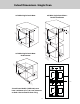
Cutout Dimensions–Single Oven Note: A minimum of 2” (5.1 cm) spacing above and below the oven is required to adjacent appliances such as a microwave or warming drawer for ventilation purposes. 27” Wide Single Undercounter 27” Wide Single Built-In 28 (71 –1/ .4 8” cm ) 25 28 (7 –1 1.4 /8” cm ) (64–1/2 .8 ” cm ) 24c”m) .9 (60 25 (64–1/2 .8 ” cm ) 24c”m) .0 (61 Ju 4 M (12-3/4 in. .
Cutout Dimensions–Single Oven 30” Wide Single French Door Double Installation 30” Wide Single French Door (104” .2 cm * * 28 28 (72–1/2 .4 ” cm ) .9 (60 (71–1/ .4 8” cm ) 28 (7 –1 * 1.4 /8” cm ) Ju nc tio LoBox n ca tio n s wall r ure ula ke s ndic Maperpe are * (104” .2 cm 4 5” 24c”m) (12 Min .7 . cm .9 (60 ) * 5” (12 Min .7 . cm ) M (12 -3/4 in. .1 ” to cm flo ) or ) 28 24c”m) (72–1/2 .4 ” cm ) s wall r ure ula ke rspendic a M pe are 3- 5 (8.
Double Oven Dimensions (For cutout dimensions - refer to pages 14 ) 27” Wide /4” 25–43cm) (65. 30” Wide 26 (67–1/2 .3 ” cm ) Rating Label Location (behind door) /4” 25–43cm) (65. 29 (74–1/2 .9 ” cm ) 5 (131–7 1.7/8” cm ) 5 (131–7 1.7/8” cm ) 2” 1/m ) – 2 c 2 2 . (57 46”cm) 6.8 (11 ” 1/2 ) 22.–2 cm (57 46”cm) .
Double Oven Dimensions (French Door Models) (For Cutout dimensions - refer to pages 15) 30” Wide French Door ” 3/4m) – 5 c 2 .4 (65 8” -7/ ) 13.2 cm (35 Rating Label Location 29 (74–1/2 .9 ” cm ) 51 (13 –7/ 1.7 8” cm ) 2” -1/cm) 2 2 2 . (57 ” 46 cm) .
Specifications & Electrical Requirements Professional Double Oven Description 27” Wide 30” Wide Overall Width 26-1/2” (67.3 cm) 29-1/2” (74.9 cm) N/A 130o 50-5/8” (128.6 cm) French Door - Full Door Swing Width Overall Height 51-7/8” (131.7 cm) Overall Depth to control panel—25-3/4” (65.4 cm) with door open (Select/Premiere models)—46” (116.8 cm) with door open (French Door model)—39-1/2” (100.3 cm) Cutout Width Standard—25-1/2” (64.8 cm) Standard—28-1/2” (72.4 cm) Flush Mount—29-15/16” (76.
Cutout Dimensions–Double Oven (Select / Premiere Models) Note: A minimum of 2” (5.1 cm) spacing above and below the oven to any adjacent appliances such as a microwave or warming drawer is required for ventilation purposes. 27” Wide Double Built-In 25 (64–1/2 .7 ” cm ) 24c”m) .9 (60 5 (120–5 8.6 /8” cm ) 30” Wide Double Built-In Ju 15 – m (38 1/4 in. .7 ” to cm flo ) or ls wal r ure cula ke rspendi a M pe are nc tio LoBox n ca tio n 28 5” (72–1/2 .4 ” cm ) (12 Min .7 . cm ) (104” .
Cutout Dimensions–Double Oven (French Door Model) Note: A minimum of 2” (5.1 cm) spacing above and below the oven to any adjacent appliances such as a microwave or warming drawer is required for ventilation purposes. (French Door models cannot be installed flush to cabinets) 30” Wide Double French Door Built-In * 28 (72–1/2 .4 ” cm ) 24c”m) (60 .9 * 5 (120–5 8.6 /8” cm ) Ju 15 s wall r ure ula ke s ndic Maperpe are – m (38 1/4 in. .7 ” to cm flo ) or nc tio LoBox n ca tio n 5” (12 Min .7 .
Dimensions (30” Single Oven flush mount installation) NOTE: French Door Models (VSOF7301) cannot be installed as a flush mount due to needed allowance for door swing clearance. LEGEND Blocking Finished Surfaces Finished Surfaces Vertical Blocking 3/4” Base Blocking F E D SINGLE OVEN FLUSH CUTOUT D 29-15/16” (76.0 cm) E 25-3/4” (65.4 cm) F 30-5/16” (77.0 cm) Note: To install the professional custom oven in a flush mount application the flush mount accessory kit is required.
Dimensions (30” Double Oven flush mount installation) NOTE: French Door Models (VDOF7301) cannot be installed as a flush mount due to needed allowance for door swing clearance. LEGEND Blocking Finished Surfaces Finished Surfaces Vertical Blocking C 3/4” Base Blocking B DOUBLE OVEN FLUSH CUTOUT A A 29-15/16” (76.0 cm) B 25-3/4” (65.4 cm) C 52-13/16” (134.1 cm) Note: To install the professional custom oven in a flush mount application the flush mount accessory kit is required.
Dimensions (30” Flush mount installation) NOTE: French Door Models cannot be installed as a flush mount due to needed allowance for door swing clearance. Top View Distance will vary depending on the cabinet Vertical Blocking C Screw Screw CRITICAL DIMENSIONS B A 18 A 29-15/16” (76.0 cm) B 2-1/2” (6.4 cm) C 1/2” (1.
Dimensions (30” Flush mount installation) NOTE: French Door Models cannot be installed as a flush mount due to needed allowance for door swing clearance. Side View Vertical Blocking LEGEND Blocking Cabinet Cross Section CRITICAL DIMENSIONS B 2-1/2” (6.4 cm) D 3” (7.
General Information • All openings in the wall behind the appliance or in the floor under the appliance should be sealed. Recommendations for Unpacking • Products are shipped on pallets with foam footings and corrugated inner-packing and exterior hoods. • Keep appliance area clear and free from combustible materials, gasoline and other flammable vapors. • Products are anchored to the pallet using metal straps that are screwed to the bottom of the product and the pallet.
Installation • BE SURE that support for this appliance is perpendicular to the front facing of the wall or cabinet before you perform the installation. Site Preparation Note: It is recommended that a thorough site inspection be conducted PRIOR to unpacking and moving this appliance. • Use of a hydraulic lift is recommended for the installation of double oven units. • WARNING: DO NOT use the handle or oven door to lift the oven.
Installation Procedure (Select / Premiere Models) 4 3 Remove hinge trim screws. Take off hinge trim. Close until pins stop door. 5 6 Lift door up and out. Repeat for all doors. Remove racks. 7 8a White Neutral Green Red Black Wiring option 1* (connect the white and green to the incoming neutral) Unscrew pallet screws from side of oven. *Note: Check local code to see which wiring option should be used when grounding the unit.
Installation Procedure (Select / Premiere Models) 8b 8c Green Neutral White White Neutral Red Green Red Black Black Wiring option 2* (connect the white to the incoming neutral, attach green to grounded junction box) Wiring option 3* (connect the white to the incoming neutral, attach green to suitable ground) 10 9 Push oven straight in. Lift oven into position. 12 11 Replace racks. Attach screws to the side of the framing.
Installation Procedure (Select / Premiere Models) 13 14 Replace door. Open door completely. Put hinge trim plates back on. Note: Screw holes may need to be re-aligned. 15 16 Take out pins. Note: To adjust door, unit must be pulled out to access adjustment screws. Turn adjustment screw clockwise (up) or counterclockwise (down). Close door.
Installation Procedure (French Door Models) 1 2 1 2 Remove wooden brace on front of pallet. Open lower door completely. Place pin in pin hole. DO NOT remove the top/single oven French Doors. 3 4 2 2 1 Close until pins stop door. Remove hinge trim screws. Take off hinge trim. 5 6 Remove racks. Lift door up and out. Repeat for all doors.
Installation Procedure (French Door Models) 8a 7 White Neutral Green Red Black Wiring option 1* (connect the white and green to the incoming neutral) Unscrew pallet screws from side of oven. 8b 8c Green Neutral White White Neutral Red Green Red Black Black Wiring option 2* (connect the white to the incoming neutral, attach green to grounded junction box) Wiring option 3* (connect the white to the incoming neutral, attach green to suitable ground) 10 9 Lift oven into position.
Installation Procedure (French Door Models) 12 11 Attach screws to the side of the framing. Note: 2 screws for single ovens, 4 screws for double ovens (screws not included). Replace racks. 14 13 Open door completely. Put hinge trim plates back on. Note: Screw holes may need to be re-aligned. Replace door. 16 15 Close door. Take out pins. Note: To adjust door turn adjustment screw clockwise (up) or counterclockwise (down).
Installation Procedure (French Door- Upper Door Adjustment) There may be ocassions where the upper doors are not aligned to the same height, especially if doors were removed for maintenance and then reinstalled. With doors in the closed position determine the alignment required, for example right door is higher than left door. Alignment procedure: 1. Open doors fully 2. Loosen bottom hinge screws on both doors, see photos below.
Performance Checklist A qualified installer should carry out the following checks: 1. Check oven bake function–bake element on full power, center and outside broil elements at partial power. Convection bake function– bake and broil elements the same with the convection fan on. 2. Check TruConvec™ function– TruConvec element (behind convection fan cover) on and convection fan on. 3. Check high broil function–both broil elements at full power. Convection broil function is the same with convection fan on. 4.
Performance Checklist Professional Series–French Door (continued) Electronic Timing Center Off/On Indicator light Self-Clean Indicator light OVEN CLEAN OFF PROOF Temperature Off/On Control Indicator light Digital Clock OVEN OFF BAKE OFF SELF CLEAN CLEAN OFF BAKE CLEAN 200 OVEN LIGHT CONV. BAKE STEAM CLEAN CONV. BAKE LOW BROIL 200 BROIL MED BROIL TRU CONVEC HI BROIL 300 CONV. ROAST CONV.
Service Information If your oven should fail to operate, check to see whether the circuit breaker is open or the fuse is blown. If service is required, call your authorized service agency. When you call for service, have the following information readily available: • Model number • Serial number • Date of purchase • Name of dealer from whom purchased Clearly describe the problem that you are having.
Viking Range, LLC 111 Front Street Greenwood, Mississippi 38930 USA (662) 455-1200 For product information call 1-888-(845-4641) or visit our web site at vikingrange.