Use / Install MANUAL Outdoor Stainless Steel Cabinets VBBO1601 / VBBO2602 / VBBO5160 / VBBO5260 VURO3200 / VBO1811 / VBO1830 / VSBO2402 / VTOP1810 VQBO4121 / VQBO5322 / VQBO5420 / VQBO5540 / VQWO4120 / VQWO5311
IMPORTANT - PLEASE READ AND FOLLOW •Before beginning, please read these instructions completely and carefully. •Do not remove permanently affixed labels, warnings, or plates from product. This may void the warranty. •Outdoor stainless steel cabinets are not designed to be water tight. Water may enter cabinetry under certain conditions •The installer should leave instructions with the consumer who should retain for future reference WARNING NEVER use LP tanks inside any stainless steel cabinetry.
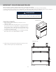
IMPORTANT - PLEASE READ AND FOLLOW! 5. Place cabinet(s) in approximate final position. Level cabinets using leveling legs. If installing two or more cabinets, use 1/2” SMS screws provided to screw them together. (See illustration #3). Illustration #3 Install (4) Tinnerman clips (provided) before fastening cabinets together. Mount cabinets with #10 x 1/2” (1.3 cm) screws provided. 6. On cabinets with interchangeable left or right hand swing, determine appropriate hinge side for cabinets.
INSTALLATION 8. If desired, snap toe kick included with each unit to front legs. (See illustration #6). Illustration #6 Snap toe kick to front legs 9. SIDE PANEL INSTALLATION (End of Run Only) •Remove all drawers. (If applicable) •Remove all protective covering from panel and install using the #10 x 1/2” tek screws provided. (See Illustration #7) •Attach toe kick to legs (See Illustration #6).
INSTALLATION 10. BACK PANEL INSTALLATION •Remove all protective covering from panel and install using the 10 x 1/2” tek screws provided. (See Illustration #8). •Attach rear toe kick to legs. (See illustration #8). NOTE: For end of the run panels, the rear, front, and side toe kicks must be modified. (See illustrations #7 & #8) Illustration #8 1. Place rear panel into area of the cabinet. 2. Attach from inside with (4) tek screws provided. (front and rear) 3.
INSTALLATION For Models VBBO5160 / VBBO5260 1. The transformer must be mounted inside the cabinet 2. If you are installing a Viking grill on either side of the burner, there is a hole on either side of the cabinet provided in order to connect the grill to the side or power burner unit. 3. If you are not are installing a Viking grill on either side, locate the four holes in the back panel and feed the AC plug through the hole in the shelf and out the hole in the rear panel. 4.
INSTALLATION Installing the Transformer on Grill Base For Models VQBO5540 1. The transformer must be mounted inside the cabinet 2. Grip the center divider between the two doors inside the cabinet and firmly pull it straight out. 3. Grip the shelf support (behind the center divider that was just removed) and firmly pull it straight out. 4. Locate the four holes in the back panel and feed the AC plug through the hole in the shelf and out the hole in the rear panel. 5.
DIMENSIONS OVERALL WIDTH (A) OVERALL HEIGHT OVERALL DEPTH VBBO1601 15 5/8” (39.7 cm) 34 1/2” (87.6 cm) 29 7/8” (75.9 cm) VBBO2602 26 3/8” (67.0 cm) 34 1/2” (87.6 cm) 29 7/8” (75.9 cm) VBBO5160 14 1/2” (36.8 cm) 34 1/2” (87.6 cm) 29 7/8” (75.9 cm) VBBO5260 20 1/4” (51.4 cm) 34 1/2” (87.6 cm) 29 7/8” (75.9 cm) VBO1811, including doors 18” (45.7 cm) 34 1/2” (87.6 cm) 29 7/8” (75.9 cm) VTPO1810, including doors 18” (45.7 cm) 34 1/2” (87.6 cm) 29 7/8” (75.
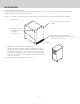
GRILL BASE DIMENSIONS Front View Opening for grill to slide into 34-1/2” (87.6 cm) A Refer to chart on previous page 29-7/8” (75.9 cm) Side View 34-1/2” (87.
SERVICE INFORMATION If service is required, call your authorized service agency. Have the following information readily available: • Model number • Serial number • Date purchased • Name of dealer from whom purchased Clearly describe the problem that you are having.
WARRANTY PROFESSIONAL SERIES OUTDOOR STAINLESS STEEL WARRANTY TWO YEAR FULL WARRANTY Outdoor cabinets and all of their component parts, except as detailed below*, are warranted to be free from defective materials or workmanship in normal residential use for a period of two (2) years from the date of original retail purchase or closing date for new construction, whichever period is longer..
Viking Range, LLC 111 Front Street Greenwood, Mississippi 38930 USA (662) 455-1200 For product information, call 1-888-(845-4641) or visit the Viking Web site at vikingrange.
Manual d’Installation/ Utilisation Petits Meubles d’Exterieur VBBO1601 / VBBO2602 / VBBO5160 / VBBO5260 VURO3200 / VBO1811 / VBO1830 / VSBO2402 / VTOP1810 VQBO4121 / VQBO5322 / VQBO5420 / VQBO5540 / VQWO4120 / VQWO5311
IMPORTANT : VEUILLEZ LIRE ET APPLIQUER •Avant de commencer, veuillez lire ces instructions complètement et avec attention. •N’enlevez pas de façon permanente des étiquettes collées, des mises en garde ou des plaques de ce produit. Cela peut annuler votre garantie. •Les pièces des armoires en acier inox pour l’extérieur ne sont pas conçues pour être étanches. De l’eau peut entrer dedans dans certaines conditions.
IMPORTANT : VEUILLEZ LIRE ET APPLIQUER 5. Placez le(s) meuble(s) à peu près à leur position finale. Mettez le(s) de niveau avec les pieds réglables. Utilisez les vis SMS fournies pour visser ensemble les meubles (voir l’illustration 3) l’illustration 3 Installer 4 agrafes Tinnerman (fournies) avant d’attacher les meubles ensemble Fixer les meubles avec les vis de 10 x 1/2” (1,3 cm) fournies l’illustration 4 6. Déterminez le côté approprié pour la charnière des meubles à ouverture de portes inversible.
INSTALLATION 8. Si vous le souhaitez, encliquetez sur les pieds à l’avant la plinthe incluse avec le meuble (voir l’illustration 6). l’illustration 6 Encliquetage de plinthe sur pieds avant 9. INSTALLATION DU PANNEAU LATÉRAL (fin de rangée uniquement) •Enlevez tous les tiroirs (s’il y a lieu). •Enlevez tout le revêtement protecteur du panneau et montez-le en utilisant les vis tek 10 x 1/2” fournies (voir l’illustration 7). •Fixez la plinthe sur les pieds (voir l’illustration 6).
INSTALLATION 10. INSTALLATION DU PANNEAU ARRIÈRE •Enlevez tout le revêtement protecteur du panneau et montez-le en utilisant les vis tek 10 x 1/2” (1,3 cm) fournies (voir l’illustration 8). •Fixez la plinthe arrière sur les pieds (voir l’illustration 8). REMARQUE : Pour extrémités de rangée, il faut adapter les plinthes latérales, avant et arrière (voir les illustrations 7 et 8). l’illustration 8 1. Placer le panneau arrière dans l’emplacement du meuble 2.
INSTALLATION Panneau latéral Pour les modèles VBBO5160/VBBO5260 1. Le transformateur doit être monté à l’intérieur de l’encadrement. 2. Si vous installez une grille Viking sur un côté du brûleur, vous trouverez un trou sur un côté de l’encadrement fourni, afin de raccorder la grille au brûleur électrique ou au brûleur latéral. 3. Dans le cas contraire, repérez les quatre trous du panneau arrière et passez la fiche CA à travers le trou de la tablette et le trou du panneau arrière. 4.
INSTALLATION Installation du transformateur Pour les modèles VQBO5540 Panneau 1. Le transformateur doit être monté à l’intérieur de latéral l’encadrement. 2. Saisissez le séparateur central entre les deux portes à l’intérieur de l’encadrement et tirez fermement pour l’extraire. 3. Saisissez le support de la tablette (derrière le séparateur central tout juste retiré) et tirez fermement pour l’extraire. 4.
SPÉCIFICATIONS DE BASE LARGEUR TOTALE HAUTEUR TOTALE PROFONDEUR TOTALE VBBO1601 15 5/8” 939,7 cm) 34 1/2” (87.6 cm) 29 7/8” (75.9 cm) VBBO2602 26 3/8” (67.0 cm) 34 1/2” (87.6 cm) 29 7/8” (75.9 cm) VBBO5160 14 1/2” (36.8 cm) 34 1/2” (87.6 cm) 29 7/8” (75.9 cm) VBBO5260 20 1/4” (51.4 cm) 34 1/2” (87.6 cm) 29 7/8” (75.9 cm) VBO1811, including doors 18” (45.7 cm) 34 1/2” (87.6 cm) 29 7/8” (75.9 cm) VTPO1810, including doors 18” (45.7 cm) 34 1/2” (87.6 cm) 29 7/8” (75.
Vue de face Ouverture pour le grill pour se glisser dans 34-1/2” (87.6 cm) A Se référer au tableau sur la page précédente 29-7/8” (75.9 cm) Vue de côté 34-1/2” (87.
INFORMATIONS SUR L’ENTRETIEN Si un entretien est nécessaire, contactez votre centre de réparation agréé. Préparez les informations suivantes de manière à ce qu’elles soient facilement disponibles : • Numéro de modèle • Numéro de série • Date d’achat • Nom du distributeur qui vous a vendu le produit Décrivez clairement votre problème.
GARANTIE GARANTIE PETITS MEUBLES D’EXTERIEUR- SÉRIE PROFESSIONNELLE GARANTIE COMPLÈTE DE DEUX ANS Les petits meubles d’extérieur et toutes leurs pièces, à l’exception de ce qui est détaillé ci-dessous*, sont garantis contre tout défaut de matériaux ou de fabrication en utilisation résidentielle normale pendant deux (2) ans à partir de la date d’achat d’origine ou la date d’achèvement d’une construction neuve, la période la plus longue étant à retenir.
Viking Range, LLC 111 Front Street Greenwood, Mississippi 38930 USA (662) 455-1200 Pour des informations sur les produits, appelez le 1-888-(845-4641) ou visitez notre site web aux États-Unis au vikingrange.
Manual de Uso y Instalación Gabinetes para Exteriores VBBO1601 / VBBO2602 / VBBO5160 / VBBO5260 VURO3200 / VBO1811 / VBO1830 / VSBO2402 / VTOP1810 VQBO4121 / VQBO5322 / VQBO5420 / VQBO5540 / VQWO4120 / VQWO5311
IMPORTANTE - POR FAVOR LEA Y CUMPLA •Antes de empezar, por favor lea completamente y cuidadosamente estas instrucciones. •No retire las etiquetas, advertencias o placas fijas del producto. Esto podría invalidar la garantía. •Los gabinetes de acero inoxidable para exteriores de Viking no están diseñados como herméticos al agua. Existen algunas condiciones en las que el agua puede penetrar en los gabinetes.
IMPORTANTE - POR FAVOR LEA Y CUMPLA 5. Coloque el gabinete(s) en la posición final aproximada. Nivele los gabinetes utilizando las patas de nivelación. Utilice tornillos para metales, de 1/2”, suministrados para unir los gabinetes mediante tornillos. (Véase la ilustración #3). Ilustración #3 Instale 4 sujetadores Tinnerman (suministrados) antes de unir los gabinetes Monte los gabinetes mediante los tornillos #10 x 1/2” (1,3 cm) suministrados Ilustración #4 6.
INSTALACIÓN 8. Si se desea, sujete a presión la tabla de base (incluida con cada unidad) a las patas delanteras. (Véase la ilustración #6). Ilustración #6 Sujete a presión la tabla de base a las patas delanteras 9. INSTALACIÓN DE PANEL LATERAL [Extremo del recorrido (tramo) únicamente] •Retire todas las gavetas. (Si es aplicable) •Retire toda la cubierta protectora del panel e instale utilizando los tornillos auto-perforantes #10 x 1/2” suministrados.
INSTALACIÓN 10. INSTALACIÓN DEL PANEL TRASERO •Retire toda la cubierta protectora del panel e instale utilizando los tornillos auto-perforantes #10 x 1/2” suministrados. (Véase la ilustración #8). •Sujete la tabla de base trasera a las patas. (Véase la ilustración #8). NOTA: Para los paneles del extremo de recorrido (tramo); las tablas de base trasera, delantera y lateral deben modificarse. (Véase las ilustraciones #7 y #8) Ilustración #8 1. Coloque el panel trasero sobre el área de gabinete 2.
INSTALACIÓN Para los modelos VBBO5160/VBBO5260 panel posterior Alimentación a la unidad Instalación del transformador Panel lateral (4) tornillos 1. El transformador debe estar montado dentro n.º 10 al 12 del gabinete 2. Si está instalando una parrilla Viking a cada lado de la hornilla, hay un orificio en cada lado del gabinete provisto para conectar la parrilla al lado o a la unidad de potencia de la hornilla. 3.
INSTALACIÓN Instalación del transformador Para los modelos VQBO5540 Alimentación a la unidad 1. El transformador debe estar montado dentro del Panel gabinete lateral 2. Sujete el divisor central entre las dos puertas dentro del gabinete y sáquelo firmemente hacia afuera. 3. Sujete el soporte del estante (detrás del divisor central que se acaba de quitar) y sáquelo firmemente hacia afuera. 4.
ESPECIFICACIONES BÁSICAS ANCHO TOTAL ALTURA TOTAL PROFUNDIDAD TOTAL VBBO1601 15 5/8” 939.7 cm) 34 1/2” (87.6 cm) 29 7/8” (75.9 cm) VBBO2602 26 3/8” (67.0 cm) 34 1/2” (87.6 cm) 29 7/8” (75.9 cm) VBBO5160 14 1/2” (36.8 cm) 34 1/2” (87.6 cm) 29 7/8” (75.9 cm) VBBO5260 20 1/4” (51.4 cm) 34 1/2” (87.6 cm) 29 7/8” (75.9 cm) VBO1811, incluyendo puertas 18” (45.7 cm) 34 1/2” (87.6 cm) 29 7/8” (75.9 cm) VTPO1810, incluyendo puertas 18” (45.7 cm) 34 1/2” (87.6 cm) 29 7/8” (75.
ESPECIFICACIONES BÁSICAS Vista frontal Apertura de la parrilla se deslice 34-1/2” (87.6 cm) A Refiérase a la tabla de la página anterior 29-7/8” (75.9 cm) Vista lateral 34-1/2” (87.
INFORMACIÓN DE SERVICIO Si se requiere servicio, llame a su agencia de servicio autorizado. Tenga a mano la siguiente información: • Número de modelo • Número de serie • Fecha de la compra • Nombre del concesionario donde hizo la compra Describa claramente el problema que tiene.
GARANTÍA GARANTÍA GABINETES PARA EXTERIORES SERIE PROFESIONAL GARANTÍA TOTAL DE DOS AÑOS Las gabinetes para exteriores y todos sus componentes, excepto como se detalla a continuación*, están garantizados como exentos defectos en materiales y fabricación con el uso residencial normal por un periodo de dos (2) años a partir de la fecha de compra original en la tienda o de la fecha de cierre de una construcción nueva, el periodo que sea más largo.
Viking Range, LLC 111 Front Street Greenwood, Mississippi 38930 USA (662) 455-1200 Para información del producto, llame al 1-888-(845-4641) o visite el sitio web de Viking en vikingrange.