R Owner’s Manual Installation and Operation Models: QV32B-A QV36B-A NOTICE DO NOT DISCARD THIS MANUAL • Important operating and maintenance instructions included. • Read, understand and follow these instructions for safe installation and operation. WARNING: If the information in these instructions is not followed exactly, a fire or explosion may result causing property damage, personal injury, or death.
Read this manual before installing or operating this appliance. Please retain this owner’s manual for future reference. A. Congratulations This owner’s manual should be retained for future reference. We suggest that you keep it with your other important documents and product manuals. Congratulations on selecting a Quadra-Fire gas fireplace, an elegant and clean alternative to wood burning fireplaces.
Safety Alert Key: • • • • DANGER! Indicates a hazardous situation which, if not avoided will result in death or serious injury. WARNING! Indicates a hazardous situation which, if not avoided could result in death or serious injury. CAUTION! Indicates a hazardous situation which, if not avoided, could result in minor or moderate injury. NOTICE: Used to address practices not related to personal injury. Table of Contents A. Congratulations . . . . . . . . . . . . . . . . . . . . . . . . . . . . . . . . .
13 Finishing A. Mantel and Wall Projections . . . . . . . . . . . . . . . . . . . . . . . 52 B. Facing Material . . . . . . . . . . . . . . . . . . . . . . . . . . . . . . . . . 53 14 Appliance Setup A. B. C. D. E. F. G. H. I. J. K. Remove Fixed Glass Assembly . . . . . . . . . . . . . . . . . . . . Remove the Shipping Materials . . . . . . . . . . . . . . . . . . . . Clean the Appliance . . . . . . . . . . . . . . . . . . . . . . . . . . . . . Accessories . . . . . . . . . . . . . . . . . . . . . . . . .
B. Limited Lifetime Warranty Hearth & Home Technologies Inc. LIMITED LIFETIME WARRANTY Hearth & Home Technologies Inc., on behalf of its hearth brands (”HHT”), extends the following warranty for HHT gas, wood, pellet, coal and electric hearth appliances that are purchased from an HHT authorized dealer.
B.
1 Listing and Code Approvals A. Appliance Certification C. BTU Specifications Models MODELS: QV32B-A, QV36B-A LABORATORY: Underwriters Laboratories, Inc. (UL) TYPE: Direct Vent Gas Fireplace Heater U.S. (0-2000 ft.) or Canada (2000-4500 ft.) QV32B-A (NG) This product is listed to ANSI standards for “Vented Gas Appliance Heaters” and applicable sections of “Gas Burning Heating Appliances for Manufactured Homes and Recreational Vehicles”, and “Gas Fired Appliances for Use at High Altitudes”.
Note: The following requirements reference various Massachusetts and national codes not contained in this document. H.
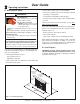
2 Operating Instructions User Guide • Keep remote controls out of reach of children. A. Gas Fireplace Safety • Never leave children alone near a hot fireplace, whether operating or cooling down. WARNING • Teach children to NEVER touch the fireplace. HOT SURFACES! Glass and other surfaces are hot during operation AND cool down. • Consider not using the fireplace when children will be present. Hot glass will cause burns.
C. Fan Kit (optional) F. Fixed Glass Assembly If desired, a fan kit may be added. Contact your dealer to order the correct fan kit. See Section 14.G. D. Clear Space G. Remote Controls, Wall Controls and Wall Switches WARNING! DO NOT place combustible objects in front of the fireplace or block louvers. High temperatures may start a fire. See Figure 2.2.
I. Lighting Instructions (Standing Pilot) FOR YOUR SAFETY READ BEFORE LIGHTING LIGHTING INSTRUCTIONS 1. Open control access panel. WARNING: If you do not follow these instructions exactly, a fire or explosion may result causing property damage, personal injury or loss of life. A. This appliance has a pilot which must be lighted by hand. When lighting the pilot, follow these instructions exactly. B. BEFORE LIGHTING, smell all around the appliance area for gas.
J. After Fireplace is Lit Initial Break-in Procedure • The fireplace should be run three to four hours continuously on high. • Turn the fireplace off and allow it to completely cool. • Remove fixed glass assembly. See Section 14.G. • Clean fixed glass assembly. See Section 3. • Replace the fixed glass assembly and run continuously on high an additional 12 hours. This cures the materials used to manufacture the fireplace. NOTICE! Open windows for air circulation during fireplace break-in.
3 Maintenance and Service Any safety screen or guard removed for servicing must be replaced prior to operating the fireplace. Doors, Surrounds, Fronts Frequency: Annually When properly maintained, your fireplace will give you many years of trouble-free service. We recommend annual service by a qualified service technician. By: Homeowner A. Maintenance Tasks-Homeowner • Inspect for scratches, dents or other damage and repair as necessary.
B. Maintenance Tasks-Qualified Service Technician Burner Ignition and Operation The following tasks must be performed by a qualified service technician. By: Qualified Service Technician Gasket Seal and Glass Assembly Inspection Frequency: Annually Frequency: Annually Tools needed: Protective gloves, vacuum cleaner, whisk broom, flashlight, voltmeter, indexed drill bit set, and a manometer. • Verify burner is properly secured and aligned with pilot or igniter.
4 Installer Guide Getting Started A. Typical Appliance System NOTICE: Illustrations and photos reflect typical installations and are for design purposes only. Illustrations/diagrams are not drawn to scale. Actual product may vary from pictures in manual HORIZONTAL TERMINATION CAP (SECTION 10.L) Note: Dual venting configurations ARE NOT allowed. Appliance MUST be vented EITHER ver tically OR horizontally. VERTICAL TERMINATION CAP (SECTION 10.
B. Design and Installation Considerations D. Inspect Appliance and Components Quadra-Fire direct vent gas appliances are designed to operate with all combustion air siphoned from outside of the building and all exhaust gases expelled to the outside. No additional outside air source is required. • Carefully remove the appliance and components from the packaging. Installation MUST comply with local, regional, state and national codes and regulations.
5 Framing and Clearances NOTICE: Illustrations reflect typical installations and are FOR DESIGN PURPOSES ONLY. Illustrations/diagrams are not drawn to scale. Actual installation may vary due to individual design preference. A. Selecting Appliance Location When selecting a location for the appliance it is important to consider the required clearances to walls (see Figure 5.1). WARNING! Risk of Fire or Burns! Provide adequate clearance around air openings and for service access.
firestops should be caulked with caulk with a minimum of 300ºF continuous exposure rating to seal gaps. Gas line holes and other openings should be caulked with caulk with a minimum of 300ºF continuous exposure rating or stuffed with unfaced insulation. If the appliance is being installed on a cement slab, a layer of plywood may be placed underneath to prevent conducting cold up into the room. B.
D. Mantel and Wall Projections WARNING! Risk of Fire! Comply with all minimum clearances as specified. Framing or finishing material closer than the minimums listed must be constructed entirely of noncombustible materials (i.e., steel studs, concrete board, etc). 3 IN. MINIMUM TOP VIEW Combustible Mantels All measurements are in inches. 5-3/8 IN. MINIMUM CEILING UNLIMITED Note: Clearance from opening to perpendicular wall. 12 11 10 9 Figure 5.5 Wall Projection (Acceptable on one side of opening.
6 Termination Locations A. Vent Termination Minimum Clearances WARNING A B 6 in. (minimum) up to 20 in. 152 mm/508 mm 18 in. minimum 457 mm 20 in. and over 0 in. minimum Fire Risk. Maintain vent clearance to combustibles as specified. • DO NOT pack air space with insulation or other materials. Failure to keep insulation or other materials away from vent pipe may cause overheating and fire. Gas, Wood or Fuel Oil Termination Cap B A* HORIZONTAL OVERHANG 2 FT. MIN. 20 INCHES MIN.
O N P R F C V Q B J H or i B V D B V V V H V X G M V A V E H V V V L A V V = VENT TERMINAL X = AIR SUPPLY INLET K C Covered Alcove Applications (Spaces open only on one side and with an overhang) = 9 inches...................clearance to outside corner E = 6 inches...................clearance to inside corner = 3 ft. (Canada) ..........not to be installed above a gas meter/regulator assembly within 3 feet horizontally from the center-line of the regulator G = 3 ft ..............
7 Vent Information and Diagrams A. Approved Pipe DO NOT mix pipe, fittings or joining methods from different manufacturers. Vertical 12 in . The pipe is tested to be run inside an enclosed wall. There is no requirement for inspection openings at each joint within the wall. 8-1/2 in. WARNING! Risk of Fire or Asphyxiation. This appliance requires a separate vent. DO NOT vent to a pipe serving a separate solid fuel burning appliance. B.
E. Use of Flex Vent The flex vent must be supported with the spacing between support intervals not exceeding 4 feet, with no more than 1/2 inch sag between supports. 3 in. CLEARANCE A support is required at each change in venting direction, and in any location where it is necessary to maintain the necessary clearance to combustibles. A simple “up and out” installation (Figure 7.3) requires only enough support to maintain the necessary clearance to combustibles.
F. Vent Diagrams Top Vent - Horizontal Termination Venting with 1 elbow (NG) V1 Minimum 90 Elbow Top Vent - Horizontal Termination Venting with 1 elbow (Propane) H1 Maximum V1 Minimum H1 Maximum 1 ft. 305 mm 1/2 ft. 152 mm 2 ft. 610 mm 1/2 ft. 152 mm 1 ft. 305 mm 1-1/2 ft. 457 mm 3 ft. 914 mm 1-1/2 ft. 457 mm 3 ft. 914 mm 2-1/2 ft. 762 mm 5 ft. 1.5 m 2-1/2 ft. 762 mm 5 ft. 1.5 m 3-1/2 ft. 1.1 m 7 ft. 2.1 m 3-1/2 ft. 1.1 m 7 ft. 2.1 m 4-1/2 ft. 1.4 m 15 ft. 4.
Top Vent - Horizontal Termination Venting with 2 elbows (Propane) Top Vent - Horizontal Termination Venting with 2 elbows (NG) V1 Minimum H1 + H2 Maximum 90 Elbow V1 Minimum 90 Elbow H1 + H2 Maximum 0 ft. 0 mm 1/2 ft. 152 mm 1 ft. 305 mm 1/2 ft. 152 mm 0 ft. 0 mm 1-1/2 ft. 457 mm 2 ft. 610 mm 1-1/2 ft. 457 mm 2 ft. 610 mm 2-1/2 ft. 762 mm 4 ft. 1.2 m 2-1/2 ft. 762 mm 4 ft. 1.2 m 3-1/2 ft. 1.1 m 6 ft. 1.8 m 3-1/2 ft. 1.1 m 6 ft. 1.8 m 4-1/2 ft. 1.4 m 14 ft. 4.
Top Vent - Horizontal Termination Venting with 3 elbows (NG) V1 Minimum 90 Elbow Top Vent - Horizontal Termination Venting with 3 elbows (Propane) H1 + H2 Maximum 0 ft. 0 mm V1 Minimum H1 + H2 Maximum 90 Elbow Not Allowed 1/2 ft. 152 mm 1 ft. 305 mm 1/2 ft. 152 mm 0 ft. 0 mm 1-1/2 ft. 457 mm 2 ft. 610 mm 1-1/2 ft. 457 mm 2 ft. 610 mm 2-1/2 ft. 762 mm 4 ft. 1.2 m 2-1/2 ft. 762 mm 4 ft. 1.2 m 3-1/2 ft. 1.1 m 6 ft. 1.8 m 3-1/2 ft. 1.1 m 6 ft. 1.8 m H1 + H2 MAX. =14 ft.
Top Vent - Vertical Termination Exhaust restrictor Instructions 1. Install the exhaust restrictor over the center of the exhaust outlet in the firebox (see Figure 7.8). No Elbow 2. Center the exhaust restrictor in the open end of the exhaust outlet and secure through the slots on the exhaust restrictor with the 2-1/4 in. self tapping screws provided in the appliance manual bag. Note: Use SLP Series components only.
Top Vent - Vertical Termination Venting with 2 elbows (NG) V1 Minimum H1 Maximum 90 Elbow 1 ft. 305 mm V2 V1 + V2 Minimum * * 1/2 ft. 152 mm 2 ft. 610 mm * * 1-1/2 ft. 457 mm 3 ft. 914 mm * * 2-1/2 ft. 762 mm 5 ft. 1.5 m * * 3-1/2 ft. 1.1 m 7 ft. 2.1 m * * 4-1/2 ft. 1.4 m 15 ft. 4.6 m * * H1 MAX. =15 ft. (4.6 m) V1+ V2 + H1 MAX. = 40 ft. (12.2 m) * No specific restrictions on this value EXCEPT V1 + V2 + H1 cannot exceed 40 ft. (12.
Top Vent - Vertical Termination Venting with 3 elbows (NG) V1 Minimum H1 Maximum 90 Elbow 0 ft. 305 mm V2 V1 + V2 Minimum * * 1/2 ft. 152 mm 2 ft. 610 mm * * 1-1/2 ft. 457 mm 3 ft. 914 mm * * 2-1/2 ft. 762 mm 5 ft. 1.5 m * * 3-1/2 ft. 1.1 m 7 ft. 2.1 m * * 4-1/2 ft. 1.4 m 15 ft. 4.6 m * * H MAX. =15 ft. (4.6 m) V1+ V2 + H1 MAX. = 40 ft. (12.2 m) * No specific restrictions on this value EXCEPT V1 + V2 + H1 + H2 cannot exceed 40 ft. (12.
Top Vent - Vertical Termination - (continued) V1 Min. Four 90º Elbows 1-1/2 ft. H1 Max. 457 mm 4 ft. 1.2 m V2 Min. 4 ft. 1.2 m H2 Max. 4 ft. 1.2 m V1 + V2 + V3 + H1 + H2 Maximum= 40 ft. (12.2 m) V3 V2 H2 Note: Use SLP Series components only. H1 Note: There MUST be a 25% reduction in total H when using flex vent except when using the simple up and out installation (see Figure 5.3). V1 Figure 7.11 30 Quadra-Fire • QV32B-A, QV36B-A • 2014-900 Rev. U • 1/12 V3 Min. 3-1/2 ft. 1.
Rear Vent - Horizontal Termination No Elbows H1 = 24 in. (711 mm) Maximum Note: Use DVP Series components only. H1 Figure 7.12 Rear Vent - Horizontal Termination Venting with 2 elbows Note: Use DVP Series components only. H1 MAX. V1 MIN. 1-1/2 ft. 457 mm Back to back elbows H2 MAX. H1 + H2 MAX. 1 ft. 305 mm 2-1/2 ft. 762 mm 3 ft. 914 mm 1 ft. 305 mm 3 ft. 914 mm 6 ft. 1.8 m 5 ft. 1.5 m 3 ft. 914 mm 5 ft. 1.5 m 10 ft. 3.0 m 7 ft. 2.1 m 5 ft. 1.5 m 7 ft. 2.1 m 14 ft. 4.
Rear Vent - Horizontal Termination Venting with 3 elbows Note: Use DVP Series components only. INSTALLED HORIZONTALLY H1 MAX. V1 MIN. H1 + H2 MAX. 1-1/2 ft. 457 mm Back to back elbows H1 + H2+ H3 MAX. 1 ft. 305 mm 2-1/2 ft. 762 mm 5-1/2 ft. 1.7 m 3-1/2 ft. 1.1 m 1 ft. 305 mm 2 ft. 610 mm 5-1/2 ft. 1.7 m 2 ft. 610 mm 4 ft. 1.2 m 9-1/2 ft. 2.9 m 7-1/2 ft. 2.3 m 3 ft. 914 mm 6 ft. 1.8 m 13-1/2 ft. 4.1 m H1 MAX. = 7-1/2 ft. (2.3 m) H1 + H2+ H3 MAX. = 13-1/2 ft. (4.
Rear Vent - Vertical Termination Venting with 2 elbows Note: Use DVP Series components only. H1 + H2 MAX V1 MIN. Back to back elbows 1/2 ft. 152 mm 2-1/2 ft. 762 mm 1 ft. 305 mm 4-1/2 ft. 1.4 m 2 ft. 610 mm 6-1/2 ft. 2.0 m 3 ft. 914 mm H MAX. = 6-1/2 ft. (2 m) V + H+ H1 MAX. = 40 ft. (12.2 m) V2 INSTALLED HORIZONTALLY H1 H2 Figure 7.16 Rear Vent - Vertical Termination Venting with 3 elbows V1 MIN. V2 Back to back elbows H1 MAX. H2 MAX. H1 + H2 MAX. 1-1/2 ft. 457 mm 1 ft.
Coaxial to Colinear Venting The coaxial to colinear adapter (DV-46DVA-GCL) is approved for installations into solid fuel masonry or factory built fireplaces that have been installed in accordance with the National, Provincial, State and local building codes. The DV-46DVA-GCL must be recessed into existing masonry fireplace. See Table 1 and Figure 7.20. OUTSIDE FACE OF FIREPLACE EXHAUST VENT PIPE TOP OF FIREPLACE OPENING 5 IN. MIN. INLET AIR VENT PIPE EXHAUST VENT PIPE 3 IN. MIN.
Connecting the DV-46DVA-GCL Adapter to Appliance Top Vent • Remove top seal cap and insulation if equipped. See Section 14, “Appliance Setup.” Attach the DV-46DVAGCL adapter to the appliance starting collar with 3-1/2 in. self-tapping screws. See Figure 7.21. Rear Vent • Remove the rear seal cap and insulation if equipped. Connect the DVP-2SL adapter to the vertically positioned elbow. Follow installation instructions included with DVP2SL kit. Secure DV-46DVA-GCL adapter to DVP-2SL with 3-1/2 in.
8 Vent Clearances and Framing A. Pipe Clearances to Combustibles B. Wall Penetration Framing WARNING! Risk of Fire! Maintain air space clearance to vent. DO NOT pack insulation or other combustibles: Combustible Wall Penetration • Between ceiling firestops • Between wall shield firestops • Around vent system Failure to keep insulation or other material away from vent pipe may cause over heating and fire. Note: Heat shields MUST overlap by a minimum of 1-1/2 in. (38 mm).
C. Install the Ceiling Firestop A ceiling firestop MUST be used between floors and attics. • DVP pipe only - Frame an opening 10 in. by 10 in. (254 mm by 254 mm) whenever the vent penetrates a ceiling/fl oor (see Figure 8.3). ATTIC ABOVE • SLP pipe only - Frame opening 9 in. x 9 in. (229 mm x 229 mm) whenever the vent penetrates a ceiling/floor (see Figure 8.3). • Frame the area with the same sized lumber as used in ceiling/floor joist.
D. Install Attic Insulation Shield WARNING! Fire Risk. DO NOT allow loose materials or insulation to touch vent. Hearth & Home Technologies Inc. requires the use of an attic shield. BEND ALL TABS INWARD 90° TO MAINTAIN CLEARANCE AND PREVENT INSULATION FROM FALLING INSIDE The National Fuel Gas Code ANSI Z223.1 and NFPA 54 requires an attic shield constructed of 26 gauge minimum metal that extends at least 2 in. (51 mm) above insulation. Attic shields must meet specified clearance and be secured in place.
9 Appliance Preparation A. Top Vent CAUTION! Risk of Cuts, Abrasions or Flying Debris. Wear protective gloves and safety glasses during installation. Sheet metal edges are sharp. Note: Actual unit may look different than the fireplace shown in this section. NOTICE: Once appliance is set up for top or rear venting, it CANNOT be changed at a later time. 2 SCREWS Figure 9.4 Remove the seal cap. Figure 9.1 For top vent, remove the two screws holding the top heat shield in place.
NOTICE: Once the seal cap has been removed it CANNOT be reattached. 2 SCREWS Figure 9.7 To attach the first section of vent pipe, make sure to use the fiberglass gasket to seal between the first vent component and the outer fireplace wrap. Use 2 self tapping screws to secure the gasket to the outer wrap. Figure 9.10 Fold the center parts of the retaining band out and use to remove the seal cap. Note: Once the vent cap has been removed, it cannot be reattached. B.
C. Securing and Leveling the Appliance WARNING! Risk of Fire! Prevent contact with: • Sagging or loose insulation • Insulation backing or plastic • Framing and other combustible materials Block openings into the chase to prevent entry of blownin insulation. Make sure insulation and other materials are secured. DO NOT notch the framing around the appliance standoffs. Failure to maintain air space clearance may cause overheating and fire.
10 Installing Vent Pipe (DVP and SLP Pipe) A. Assemble Vent Sections (DVP Pipe Only) Attach Vent to the Firebox Assembly Note: The end of the pipe sections with the lanced tabs will face toward the appliance. Attach the first pipe section to the starting collar: • Lanced pipe end to the starting collar • Inner pipe over inner collar • Push the pipe section until all lanced tabs snap in place • Lightly tug on pipe to confirm it has locked.
B. Assemble Vent Sections (SLP Pipe Only) C. Assemble Slip Sections To attach the first vent component to the starting collars of the appliance: • Slide the inner flue of the slip section into the inner flue of the pipe section and the outer flue of the slip section over the outer flue of the pipe section. See Figure 10.6. • Lock the vent components into place by sliding the pipe section onto the collar. • Slide together to the desired length.
D. Secure the Vent Sections E. Disassemble Vent Sections • Vertical runs of DVP pipe must be supported every 8 ft. (2.44 m) after the 25 ft. (7.62 m) maximum unsupported rise. • Rotate either section (see Figure 10.10) so the seams on both pipe sections are aligned as shown in Figure 10.11. • Vertical runs of SLP pipe must be supported every 8 ft. (2.44 m). • Pull carefully to separate the pieces of pipe. • Horizontal sections must be supported every 5 feet (1.52 m).
F. Install Decorative Ceiling Components (SLP only) LEVEL A decorative ceiling thimble can be installed on a flat ceiling through which the vent passes. The decorative ceiling thimble is used to cover the firestop. CATHEDRAL CEILING SUPPORT BOX • Seal the gap between the vent pipe and firestop using silicone with a minimum of 300ºF continuous exposure rating to prevent cold air infiltration.
G. Install Metal Roof Flashing • See minimum vent heights for various pitched roofs (Figure 10.14) to determine the length of pipe to extend through the roof. CAULK • Slide the roof flashing over the pipe sections extending through the roof as shown in Figure 10.15. HORIZONTAL OVERHANG 2 FT. MIN. 20 INCHES MIN. VERTICAL WALL LOWEST DISCHARGE OPENING Figure 10.15 GAS DIRECT VENT TERMINATION CAP X 12 ROOF PITCH IS X/ 12 H (MIN.
I. Install Vertical Termination Cap • Attach the vertical termination cap by sliding the inner collar of the cap into the inner flue of the pipe section while placing the outer collar of the cap over the outer flue of the pipe section. • Secure the cap by driving three self-tapping screws (supplied) through the pilot holes in the outer collar of the cap into the outer flue of the pipe (see Figure 10.18). TERMINATION CAP K.
L. Install Horizontal Termination Cap (DVP and SLP Pipe) WARNING! Risk of Fire! The telescoping flue section of the termination cap MUST be used when connecting vent. • 1-1/2 (38 mm) minimum overlap of flue telescoping section is required. Failure to maintain overlap may cause overheating and fire. Note: When using termination caps with factory-supplied heat shield attached, no additional wall shield firestop is required on the exterior side of a combustible wall.
11 Gas Information A. Fuel Conversion C. Gas Connection • Make sure the appliance is compatible with available gas types. • Refer to Reference Section 16 for location of gas line access in appliance. • Conversions must be made by a qualified service technician using Hearth & Home Technologies specified and approved parts. • Gas line may be run through knockout(s) provided. B. Gas Pressure • Optimum appliance performance requires proper input pressures.
12 Electrical Information A. Wiring Requirements C. Optional Accessories Requirements NOTICE: This appliance must be electrically wired and grounded in accordance with local codes or, in the absence of local codes, with National Electric Code ANSI/NFPA 70-latest edition or the Canadian Electric Code CSA C22.1. • This appliance may be used with a wall switch, wall mounted thermostat and/or a remote control. • Wire the appliance junction box to 110-120 VAC.
E. Junction Box Installation If the box is being wired from the INSIDE of the appliance: Romex Connector • Remove the screw attaching the junction box/receptacle to the outer shell, rotate the junction box inward to disengage it from the outer shell (see Figure 12.2). 14/2WG • Pull the electrical wires from outside the appliance through the opening into the valve compartment and secure wires with a Romex connector. See Figure 12.2.
13 Finishing A. Mantel and Wall Projections WARNING! Risk of Fire! Comply with all minimum clearances as specified. Framing closer than the minimums listed must be constructed entirely of noncombustible materials (i.e., steel studs, concrete board, etc.). 3 IN. MINIMUM TOP VIEW Combustible Mantels All measurements are in inches. 5-3/8 IN. MINIMUM CEILING UNLIMITED Note: Clearance from opening to perpendicular wall. 12 11 10 9 Figure 13.3 Wall Projection (Acceptable on one side of opening.
B. Facing Material • Metal front faces may be covered with non-combustible materials only. • Facing and/or finishing materials must not interfere with air flow through louvers, operation of louvers or doors, or access for service. • Facing and/or finishing materials must never overhang into the glass opening. • Observe all clearances when applying combustible materials. • Seal joints between the finished wall and appliance top and sides using a 300ºF minimum sealant. Refer to Figure 13.5.
14 Appliance Setup A. Remove Fixed Glass Assembly E. Ember Placement See Section 14.G. WARNING! Risk of Explosion! Follow ember placement instructions in manual. DO NOT place embers directly over burner ports. Replace ember material annually. Improperly placed embers interfere with proper burner operation. B. Remove the Shipping Materials Remove shipping materials from inside or underneath the firebox. C.
F. Install the Log Assembly If the gas logs have been factory installed they should not need to be positioned. If the logs have been packaged separately, refer to the following instructions. 2 4 1 Log Set Assembly: LOGS-2014 Model: QV32B-A 5 1 3 STEP 1: Carefully remove the logs from the packaging. CAUTION: Logs are fragile! 2 STEP 3: LOG #2 (SRV2014-703): Place log # 2 with the left tip of the log on the flat spot on the burner and the right end pulled forward against grate.
Install the Log Assembly If the gas logs have been factory installed they should not need to be positioned. If the logs have been packaged separately, refer to the following instructions. Log Set Assembly: LOGS-2016 Model: QV36B-A 1 1 4 2 5 3 SAME LOG STEP 2: LOG #1 (SRV2016-701): Place notches of log #1 on outer two grate tines, and push against back of firebox. STEP 1: Carefully remove the logs from the packaging.
G. Fixed Glass Assembly J. Install Hood WARNING! Risk of Asphyxiation! Handle fixed glass assembly with care. Inspect the gasket to ensure it is undamaged and inspect the glass for cracks, chips or scratches. The hood is shipped with the front/door. • DO NOT strike, slam or scratch glass. • DO NOT operate fireplace with glass removed, cracked, broken or scratched. • Replace as a complete assembly. K.
15 Troubleshooting With proper installation, operation, and maintenance your gas appliance will provide years of trouble-free service. If you do experience a problem, this troubleshooting guide will assist a qualified service technician in the diagnosis of a problem and the corrective action to be taken. This troubleshooting guide can only be used by a qualified service technician. Contact your dealer to arrange a service call by a qualified service technician. A.
Troubleshooting (continued) Symptom 3. (Continued) Possible Cause Corrective Action C. Valve. Turn the valve knob to the ON position. Place the ON/ OFF switch in the ON position. Take a reading with a millivolt meter at the thermopile terminals. The millivolt meter should read greater than 125mV. If the reading is acceptable, and if the burner does not come on, replace the gas valve. D. Plugged burner orifice. Check the burner orifice for stoppage. Remove stoppage. E. Wall switch or wires.
16 Reference Materials A. Appliance Dimension Diagram Dimensions are actual appliance dimensions. Use for reference only. For framing dimensions and clearances refer to Section 5.
B. Vent Components Diagrams Pipe DVP4 Effective Height/Length DVP Pipe (see chart) Effective Length Inches Millimeters 4 102 10-1/2 in. (267 mm) 45 ° DVP6 6 152 DVP12 12 305 DVP24 24 610 DVP36 36 914 DVP48 48 1219 10-7/8 in. (276 mm) DVP45 (45º Elbow) 4-7/8 in. ( 276 mm) DVP6A 3 to 6 76 to 152 DVP12A 3 to 12 76 to 305 DVP12MI 3 to 12 76 to 305 DVP24MI 3 to 24 76 to 610 11-3/8 in. (289 mm) 10 in. (254 mm) 1 in. (25 mm) 7-3/8 in. (187 mm) 1-1/4 in. (32 mm) 10 in.
B. Vent Components Diagrams (continued) Note: Heat shields MUST overlap by a minimum of 1-1/2 in. (38 mm). The heat shield is designed to be used on a wall 4 in. to 7-1/4 in. (102 mm to 184 mm) thick. If wall thickness is less than 4 in. (102 mm) the existing heat shields must be field trimmed. If wall thickness is greater than 7-1/4 in. (184 mm) a DVP-HSM-B will be required. 8 in. (203 mm) Heat Shield 15-1/8 in. (384 mm) Term Cap Max Effective Length 12 in.
B. Vent Components Diagrams (continued) 31 in. (787 mm) 13-1/4 in. (367 mm) 24-5/8 in. (625 mm) 27-1/2 in. (127 mm) 24-5/8 in. (625 mm) 13-1/4 in. (367 mm) RF6M Roof Flashing Multi-pak RF12M Roof Flashing Multi-pak 5 in. (127 mm) 13-3/4 in. (349 mm) 11-7/8 in. (302 mm) 5 in. (127 mm) 13-7/8 in. (352 mm) 13-3/4 in. (349 mm) DVP-BEK2 DVP-HPC Cap Brick Extension BEK Trap Cap Brick Extension 11-5/8 in. (295 mm) 12-1/8 in. (308 mm) 7-1/8 in. (181 mm) 5-3/4 in.
B. Vent Components Diagrams (continued) 6-1/2 in. 165 mm 6-1/2 in. 165 mm 8-3/4 in. 222 mm 6-1/2 in. 165 mm 9-1/4 in. 235 mm 6 in. 152 mm 6-5/8 in. 168 mm SLP45 45° Elbow 6-5/8 in. 168 mm 9-7/8 in.
B. Vent Components Diagrams (continued) Note: Heat shields MUST overlap by a minimum of 1-1/2 in. (38 mm). The heat shield is designed to be used on a wall 4 in. to 7-1/4 in. (102 mm to 184 mm) thick. If wall thickness is less than 4 in. (102 mm) the existing heat shields must be field trimmed. If wall thickness is greater than 7-1/4 in. (184 mm) a DVP-HSM-B will be required. 8 in. (203 mm) Heat Shield 15-1/8 in. (384 mm) Term Cap Max Effective Length 12 in.
B. Vent Components Diagrams (continued) COAXIAL to COLINEAR VENTING LINK-DV30B Flex Liner Kit DV-46DVA-GCL Coaxial/Colinear Appliance Connector Figure 16.7 Coaxial to Colinear Vent Components 66 Quadra-Fire • QV32B-A, QV36B-A • 2014-900 Rev.
D. Contact Information R Quadra-Fire, a brand of Hearth & Home Technologies Inc. 7571 215th Street West, Lakeville, MN 55044 www.quadrafire.com Please contact your Quadra-Fire dealer with any questions or concerns. For the location of your nearest Quadra-Fire dealer, please visit www.quadrafire.com.