
Owner`s manual


Quadra-Fire • QVI-30FB • 2020-900 Rev. H • 9/07
18
Serving the blower
On units already installed removal of decorative front, sur-
round and gas insert is required.
• Detach flexible liner from the top of unit.
• Remove the four screws on the coverplate (see Figure 11).
• Bend up the tabs on the base pan (see Figure 10).
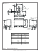
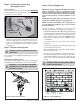
Figure 9.
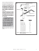
Junction box installation
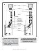
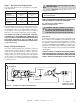
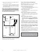
Figure 10. Fan Wiring Diagram
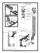
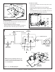
Figure 11.
NOTE: IF ANY OF THE ORIGINAL WIRE AS SUP-
PLIED WITH THE APPLIANCE MUST BE RE-
PLACED, IT MUST BE REPLACED WITH TYPE
105
0
C RATED WIRE.
JUNCTION BOX
VARIABLE SPEED CONTROL
TEMPERATURE
SENSOR SWITCH
WHT
GRN
BLK
BLK
110-120 VAC
BLOWER
BLOWER RECEPTACLE
BLK
BLK
BLK
BLK
WHT
GROUND
WHT
BLK
BLK
BLK
REMOTE
RECEPTACLE
FAN
COVER
PLATE
GROUND
WIRE
JUNCTION
BOX
SIDEWALL
FEED PLUG
THROUGH HOLE
INSERT STRAIN RELIEF
AROUND CORD IN THIS END
FROM OUTSIDE OF UNIT
SCREW
PROVIDED
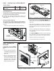
To service or clean:
• Remove the ground wire of the fan can clip on the side of
the base pan.
• Remove the blower in between the bend up tabs.
• Install and wire the blower per instruction shipped with
the fan.
• Reinstall the blower in reverse order. Make sure the fan
does not make contact with the back wall.
FAN
TEMPERATURE
SENSOR SWITCH
SPEED CONTROL
(RHEOSTAT)
JUNCTION
BOX
GROUND WIRE
(ATTACH TO ANY
METAL SURFACE)
BEND UP
TABS
REMOTE
OUTLET
FAN
OUTLET