ENIGMA IP2 Monitoring Receiver (and IP receiver card) Programming Manual 6 / 11 / 2014
CONTENT 1. INTRODUCTION.......................................................................................................................3 2. SYSTEM STRUCTURE.............................................................................................................4 3. FIRST STEPS..............................................................................................................................4 Connectors and LED signals......................................................................
1. INTRODUCTION Thank you for choosing our product. This modern and reliable monitoring receiver not only guarantees the highest level of security, but also it is a useful colleague in the life of every monitoring company, because of its user-friendly handling and intelligent functions. To use the highest range of provided functions please read carefully the Installer Manual.
2. SYSTEM STRUCTURE The Enigma IP2 monitoring receiver is ideal and cost-effective solution to build-up a monitoring station, where transmission is sent only through IP / GPRS channel. Device has compact size and excellent parameter setting possibilities. The incoming IP communication might be monitored according to client accounts. It provides prominent protection level for the reliable and secure operation. The card version device can be be built into the Enigma II base unit.
Connectors and LED signals There are the following connectors on the backside of the receiver: Power supply connector: 12 VDC power supply connector (always use the original power supply unit provided by manufacturer). Note: In case of the failure of main power supply unit, the device is able to operate with power received through USB cable (if USB current is suitable). But long term usage without main power supply unit is not recommended. Ethernet connector: 100 Mbit Ethernet connector for network cable.
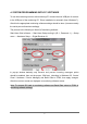
4. SYSTEM PROGRAMMING WITH PC SOFTWARE To use the monitoring receiver with monitoring PC connect the mini USB port of receiver to the USB port of the monitoring PC. Driver installation is automatic (from Windows 7). After this the appropriate monitoring software settings should be done (it means usually the serial port and baud rate settings).
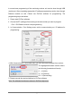
In normal case programming of the monitoring receiver unit can be done through USB (serial) port. After completing appropriate IP settings programming can be done through Ethernet network as well. Please use EniTerm software for programming. The programming steps are bellow: 1. Please start EniTerm software. 2. Choose the ET (settings) file according to the device what you want to program: - IP.et – IP2 Ethernet receiver card programming 3.
6. Click to Communication / Write Data menu to send the modified settings to receiver. Note: During data reading (and sending) receiver firmware version can be checked. 5. TROUBLESHOOTING TROUBLE: Any abnormal operation in functions during the usage of the device. SOLUTION: Firmware upgrade with the newest firmware file usually solve these kind of problems (see Firmware update part in manual). TROUBLE: No connection between monitoring PC and receiver unit.
6. ENIGMA IP2 TESTING When all setting is finished it is possible to test ENIGMA IP2 unit. Testing is also useful to test data sending from an external installation place. The testing software in the given local network can help a lot to check monitoring transmission and find the reason of possible problems. For test please use ipt.exe software in the following way: 1. Enter the IP address or Domain name of the monitoring station. 2.
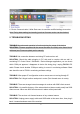
Received events in Enigma IP2 can be checked easily with a simple web browser access. For this IP address (and port if it is different from 80) of Enigma IP2 unit should be typed in a web browser (Internet Explorer recommended). Then receiver HTTP page can be seen. Note: For the operation of event list review through web browser the IP ADDRESS and HTTP PORT should be enabled in rooter as well. In Accounts menu you can check the accounts for IP monitoring (if enabled).
7. FIRMWARE UPGRADE AND OTHER FUNCTIONS It is recommended to upgrade regularly firmware of the unit to use new functions and eliminate possible bugs. Firmware upgrade can be done by the following steps: 1. Get the latest firmware files from your distributor (ip.ipx file). 2. Save settings from the IP card planned to update with EniTerm software (please check 4. System programming with PC software chapter). Please close monitoring software if it is running. 3.
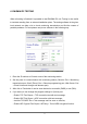
5. The following window will pop up if you use IP Card update. 6. Choose the COM port where IP card is connected. Note: The baudrate should be set to 57600 in case of IP card update. IP card update through Ethernet is only possible through local network. 7. After clicking to Connect menu, then Load File menu you should select ip.ipx firmware file for update. 8. Upgrade process can be started with Update button. Click To Disconnect button at the end of update proccess. 9.
8.
IP RESTORE 3692 IP communication restored for the given client account where communication was lost Z0 The given client account was deleted on web browser Z9 The given account was modified on web browser Note.: System messages are sent with 0000 client account (except IP ERROR / IP RESTORE messages, which are sent with the given client account where IP communication was lost). 9.
10. TECHNICAL DATA Product ENIGMA IP2 Power supply 12 Vdc @ 500 mA Maximum current consumption about 250 mA Event buffer up to 20.000 events Monitored IP devices up to 2.