Service Manual Model #: VIZIO L42HDTV10A VIZIO GV42L HDTV V, Inc 320A Kalmus Drive Costa Mesa, CA 92626 TEL : +714-668-0588 FAX :+714-668-9099 Top Confidential
Table of Contents CONTENTS PAGE Sections 1. Features 1-1 2. Specifications 2-1 3. On Screen Display 3-1 4. Factory Preset Timings 4-1 5. Pin Assignment 5-1 6. Main Board I/O Connections 6-1 7. Theory of Circuit Operation 7-1 8. Waveforms 8-1 9. Trouble Shooting 9-1 10. Block Diagram 10-1 11. Spare parts list 11-1 12-1. Complete Parts List (L42 HDTV10A _LG) 12-1 12-2. Complete Parts List (GV42L HDTV_LG) 12-2 Appendix 1. Main Board Circuit Diagram 2. Main Board PCB Layout 3.
VINC Service Manual VIZIO L42HDTV10A,GV42L HDTV COPYRIGHT © 2000 V, INC. ALL RIGHTS RESERVED. IBM and IBM products are registered trademarks of International Business Machines Corporation. Macintosh and Power Macintosh are registered trademarks of Apple Computer, Inc. VINC and VINC products are registered trademarks of V, Inc. VESA, EDID, DPMS and DDC are registered trademarks of Video Electronics Standards Association (VESA).
Chapter 1 Features 1. Built in TV channel selector for TV viewing. 2. Simulatnueous display of PC and TV images. 3. Connectable to PC’s analog RGB port . 4. Built in S-video, HDTV, composite video, HDMI and TV out. 5. Built in auto adjust function for automatic adjument of screen display. 6. Smoothing function enables display of smooth texts and graphics even if image withresolution lower than 1366x768 is magnified. 7. Picture In Picture (PIP) funtion to show TV or VCR images. 8.
Chapter 2 Specification 1. LCD CHARACTERISTICS Type: 42.0 WXGA TFT LCD Size: 42.02inch Display Size: 42.02 inches (1067.308mm) diagonal Outline Dimension: 1006 mm (H) x 610 mm (V) x 56 mm (D) (Typ.) Pixel Pitch: 0.227mm x 0.681mm x RGB Pixel Format: 1366 horiz. By 768 vert. Pixels RGB strip arrangement Contrast ratio: 1.CR : 550(Typ) 2.
.Speaker Output 10W (max) X2 7. ENVIRONMENT 5-1. Operating Temperature: 5c~35c (Ambient) 5-2. Operating Humidity: Ta= 35 °C, 90%RH (Non-condensing) 5-3. Operating Altitude: 0 - 14,000 feet (4267.2m)(Non-Operating) 8. DIMENSIONS (Physical dimension) Width: 1066 mm. Depth: 269.2mm Height: 765.4mm 9. WEIGHT (Physical weight) a. Net: 36.0+/-0.5kgs b. Gross: 43+/-0.5kgs 9-1. MOUNTING PRECAUTIONS (1) You must mount a module using holes arranged in four corners or four sides.
(6) Do not touch, push or rub the exposed polarizes with glass, tweezers or anything harder than HB pencil lead. And please do not rub with dust clothes with chemical treatment. Do not touch the surface of polarizer for bare hand or greasy cloth.(Some cosmetics are detrimental to the polarizer.) (7) When the surface becomes dusty, please wipe gently with absorbent cotton or other soft materials like chamois soaks with petroleum benzene.
9-3. HANDLING PRECAUTIONS FOR PROTECTION (1) The protection film is attached to the bezel with a small masking tape. When the protection film is peeled off, static electricity is generated between the film and polarizer. This should be peeled off slowly and carefully by people who are electrically grounded and with well ion-blown equipment or in such a condition, etc.
Chapter 3 On Screen Display Main unit button Power MENU CH ▲ CH ▼ VOL + VOL Input TV Source A. Picture Adjust: a. Picture Mode (Standard/Movie /Game / Custom) b. Backlight (0~100) c. Contrast (0~100) d. Brightness (0~100) e. Color (saturation)(0~100) f. Tint (hue) (0~100) g. Sharpness (0~7) h. Color Temperature (Cool/Normal/Warm/Custom) i. Advanced Picture Adjust B. Audio Adjust: a. Volume (0~100) b. Bass (0~100) c. Treble (0~100) d. Balance (0~100) e. Surround (ON/OFF) f.
C. Special Features: a. Language (English/Français/Espaňol) b. Sleep Timer (OFF/30Min/60Min/90Min/120Min) c. Analog CC (OFF/CC1~4/TT1~4) d. Digital CC (OFF/CC1~4/Service1~6) e. Digital CC Style f. PIP Position (TL/TC/TR/ML/MR/BL/BC/BR) g. Rest All Setting D. TV Tuner Setup: a. Tuner Mode (Cable/Air) b. Auto Search c. Skip Channel d. Digital Audio Out (PCM/Dolby Digital) e. Time Zone (Eastern/Indiana/Central/Mountain/Arizona/Pacific/Alaska/Hawaii) E. Parental Control: a. Parental Lock Enable (ON/OFF) b.
B. Audio Adjust: a. Volume (0~100) b. Bass (0~100) c. Treble (0~100) d. Balance (0~100) e. Surround (ON/OFF) f. Speakers (ON/OFF) C. Special Features: a. Language (English/Français/Espaňol) b. Sleep Timer (OFF/30Min/60Min/90Min/120Min) c. PIP Position (TL/TC/TR/ML/MR/BL/BC/BR) d. Rest All Setting AV COMPONENT MODE A. Picture Adjust: a. Picture Mode (Standard/Movie /Game / Custom) b. Backlight (0~100) c. Contrast (0~100) d. Brightness (0~100) e. Color (saturation)(0~100) f. Tint (hue) (0~100) g.
C. Special Features: a. Language (English/Français/Espaňol) b. Sleep Timer (OFF/30Min/60Min/90Min/120Min) c. Analog CC (OFF/CC1~4/TT1~4) d. PIP Position (TL/TC/TR/ML/MR/BL/BC/BR) e. Rest All Setting D. Parental Control: a. Parental Lock Enable (ON/OFF) b. TV Rating c. Move Rating d. Block Unrated TV (NO/Yes) e. Access Code Edit HDMI MODE: A. Picture Adjust: a. Picture Mode (Standard/Movie /Game / Custom) b. Backlight (0~100) c. Contrast (0~100) d. Brightness (0~100) e. Color (saturation)(0~100) f.
C. Special Features: a. Language (English/Français/Espaňol) b. Sleep Timer (OFF/30Min/60Min/90Min/120Min) c. PIP Position (TL/TC/TR/ML/MR/BL/BC/BR) d. Rest All Setting CONFIDENTIAL – DO NOT COPY Page 3-5 File No.
Chapter4 Factory preset timings This timing chart is already preset for the TFT LCD analog & digital display monitors. Refresh Horizontal Vertical Horizontal Vertical Pixel rate Frequency Frequency Polarity Polarity Rate 640x480 60Hz 31.5kHz 59.94Hz N N 25.175 640x480 75Hz 37.5kHz 75.00Hz N N 31.500 800X600 60Hz 37.9kHz 60.317Hz P P 40.000 800x600 75Hz 46.9kHz 75.00Hz P P 49.500 800X600 85Hz 53.7kHz 85.06Hz P P 56.250 1024x768 60Hz 48.4kHz 60.
Chapter 5 Pin Assignment The TFT LCD analog display monitors use a 15 Pin Mini D-Sub connector as video input source. Pin Description 1 Red 2 Green 3 Blue 4 Ground 5 Ground 6 R-Ground 7 G-Ground 8 B-Ground 9 +5V for DDC 10 Ground 11 No Connection 12 (SDA) 13 H-Sync (Composite Sync) 14 V-Sync 15 (SCL) 1 5 6 11 CONFIDENTIAL – DO NOT COPY 10 15 Page 5-1 File No.
HDMI CONNECT PIN ASSIGNMENT PIN SIGNAL ASSIGNMENT 1 TMDS Data2+ 2 TMDS Data2 Shield 3 TMDS Data2- 4 TMDS Data1+ 5 TMDS Data1 Shield 6 TMDS Data1- 7 TMDS Data0+ 8 TMDS Data0 Shield 9 TMDS Data0- 10 TMDS Clock+ 11 TMDS Clock Shield 12 TMDS Clock- 13 CEC 14 Reserved (N.C on device) 15 SCL 16 SDA 17 DDC/CEC Ground 18 +5V Power 19 Hot Plug Detect CONFIDENTIAL – DO NOT COPY Page 5-2 File No.
Four-Pin mini DIN S-Video Connector a. Pin Assignment b. Signal Level Video (Y): Analog 0.1Vp-p/75Ω Video (C): Analog 0.286p-p/75 Sync (H+V): 0.3V below Video (Y) c. Frequency H: 15.734KHz V: 60Hz (NTSC) Signal Level Video (Y) : Analog 0.1Vp-p/75Ω Video (C) : Analog 0.286p-p/75Ω Sync (H+V): 0.3V below Video (Y) Frequency H: 15.734Khz V: 60HZ (NTSC) F-Type TV RF connector a. Signal Level 60dBµV typical b. System NTSC c. Frequency 55~801MHz (NTSC) PC connector 15 pin male D-sub connector a.
RGB Signal: a. Sync Type TTL (Separate / Composite) or Sync. On Green b. Sync polarity Positive or Negative c. Video Amplitude RGB: 0.7Vp-p d. Frequency H: support to 30K~70KHz V: support to 50~85Hz Pixel Clock: support to 110MHz HDMI Signal (HDMI): a. Pin Assignment Refer to HDNI Pin Assignment b. Type A c. Polarity Positive or Negative d. Frequency H: 15.
Chapter 6 Main Board I/o Connections J6 CONNECTION (TOP→BOTTOM) Pin Description 1 “+5V” 2 “+3.3V” 3 “ADCKEY” 4 “LED” 5 “PWR KEY” 6 “GND” 7 “GND” 8 “IR” J7 CONNECTION (TOP→BOTTOM) Pin Description 1 “POWRSW” 2 “+12V” 3 “+12V” 4 “+12V” 5 “GND” 6 “GND” 7 “GND” 8 “GND” 9 “GND” 10 “+5V” 11 “+5V” 12 +5V 13 “PWM” 14 “BL ON/OFF” CONFIDENTIAL – DO NOT COPY Page 6-1 File No.
Chapter 7 Theory of Circuit Operation The operation of D-SUB 15pin route The D-SUB 15pin is input analog signal to the MTK8202 transfer A/D converter then generates the vertical and horizontal timing signals for display device. The operation of HDMII CON route The HDMI 1&2 CON is input digital signal to the PI3HDMI412FT switch output signal is process to the MT8293. Then transfer to the MTK8202, the MTK8202 generates the vertical and horizontal timing signals for display device.
MT8202 Application MT8202 is a highly integrated video and audio single chip processor for emerging HDTV-Ready LCD TV. It includes one 3D/2D TV Decoder recovering the best image from CVBS, and in addition, its analog input also support popular S-Video, Component, VGA video source. On-chip advanced motion adaptive de-interlacer (MDDitm) converts accordingly the interlace video into smooth non-flicking progressive motion pictures.
1. Video input a. Input Multiplexing 1.component X2 2.composite X2 3.s-videoX1 4.HDMI X2 5.VGA X1 6.RF&DTV X1 b. Input formats: 1.support HDTV 480i/480p/720p/1080p 2.support Y/C signal 1VP-P/75Ω 3.support Y/C signal 1VP-P/75Ω 4.support 480i/408p/720p/1080i/1080p 5.support VGA input up to 1366x168@60HZ 6.support RF NTSC system Frequency 55~801MHZ;DTV 480i/480p/720p/1080p 2. Decoder TVD 1.Single 2nd generation TV decoder 2.Automatic TV standard detection supporting NTSC, NTSC-4.
VGA 1.Supporting various VGA input timings up to SXGA (1280x1024@75Hz). 2.Supporting Separate/Composite/SOG sync types Digital port 1.1 digital port supporting DVI 24-bit RGB or CCIR-656/601 digital video input format 2.1 additional 8 bit digital port for ITU656 video format VBI 1.Dual VBI decoders for the application of V-Chip/Closed-Caption/XDS/ Teletext/WSS/VPS 2.Supporting external VBI decoder by YPrPb input 3.VBI decoder up to 1000 pages Teletext. 3. Support Formats: Support NTSC, NTSC-4.
BOLOCK DIAGRAM 4. 2D-Graphic/OSD processor Embedded two backend RGB domain OSD planes and one YUV domain OSD plane. to support Main/PIP Teletext/Close-caption functions together with setup menu 1.Supporting alpha blending among these two planes and video 2.Supporting Text/Bitmap decoder 3.Supporting line/rectangle/gradient fill 4.Supporting bitblt 5.Supporting color Key function 6.Supporting Clip Mask 7.65535/256/16/4/2-color bitmap format OSD, 8.Automatic vertical scrolling of OSD image 9.
5. Microprocessor interface When power is supplied and power key is pressed then the rest circuit lets Reset to low state that will reset the MTK8202 to initial state. After that the Reset will transits to high state and the MTK8202 start to work that microprocessor executes the programs and configures the internal registers. The execution speed of CPU is 162 MHz. 1.
6. Video processor 1.Color Management Fully 10-bit processing to enhance the video quality Advanced flesh tone and multiple-color enhancement. (For skin, sky, and grass…) Gamma/anti-Gamma correction Advanced Color Transient Improvement (CTI) Saturation/hue adjustment 2.Contrast/Brightness/Sharpness Management Sharpness and DLTI/DCTI Brightness and contrast adjustment Black level extender White peak level limiter Adaptive Luma/Chroma management 3.
6.Seamless performance comparing demonstration function Support Left/Right video processing comparing function without additional resources (DRAM…) for customers’ demonstration All the video functions (De-interlace/3D comb/NR/Flesh tone/CTI) can be included 7. DRAM Usage 1.For features of 8202, Dual for enhance features support, and single 8x16 DDR for simple function support Lists are the comparison chart between function support lists of (2xDDR) and (1xDDR) 2.
8.DDR SDRAM (V58C2128164SBI5) Application CONFIDENTIAL – DO NOT COPY Page 7-9 File No.
Pin description CONFIDENTIAL – DO NOT COPY Page 7-10 File No.
Command Truth Table 1. Power-Up Functional Description The following sequence is required for POWER UP. 1. Apply power and attempt to maintain CKE at a low state (all other inputs may be undefined.) - Apply VDD before or at the same time as VDDQ. - Apply VDDQ before or at the same time as VTT & Vref. 2. Start clock and maintain stable condition for a minimum of 200us. 3. The minimum of 200us after stable power and clock (CLK, CLK), apply NOP & take CKE high. 4. Precharge all banks. 5.
2. Mode Register Set (MRS) The mode register stores the data for controlling the various operating modes of DDR SDRAM. It programs CAS latency, addressing mode, burst length, test mode, DLL reset and various vendor specific options to make DDR SDRAM useful for a variety of different applications. The default value of the mode register is not defined, therefore the mode register must be written after EMRS setting for proper DDR SDRAM operation.
3. Precharge The Auto Precharge operation can be issued by having column address A10 high when a Read or Write command is issued. If A10 is low when a Read or Write command is issued, then normal Read or Write burst operation is executed and the bank remains active at the completion of the burst sequence. When the Auto Precharge command is activated, the active bank automatically begins to precharge at the earliest possible moment during the Read or Write cycle once tRAS(min) is satisfied.
4. Bank Activate Command The Bank Activate command is issued by holding CAS and WE high with CS and RAS low at the rising edge of the clock. The DDR SDRAM has four independent banks, so two Bank Select addresses (BA0 and BA1) are supported. The Bank Activate command must be applied before any Read or Write operation can be executed. The delay from the Bank Activate command to the first Read or Write command must meet or exceed the minimum RAS to CAS delay time (tRCD min).
5. Read Operation With the DLL enabled, all devices operating at the same frequency within a system are ensured to have the same timing relationship between DQ and DQS relative to the CK input regardless of device density, process variation, or technology generation. The data strobe signal (DQS) is driven off chip simultaneously with the output data (DQ) during each read cycle.
7.Precharge Timing During Write Operation Precharge timing for Write operations in DRAMs requires enough time to satisfy the write recovery requirement. This is the time required by a DRAM sense amp to fully store the voltage level. For DDR SDRAMs, a timing parameter (tWR) is used to indicate the required amount of time between the last valid write operation and a Precharge command to the same bank.
9. Burst Write Operation The Burst Write command is issued by having CS, CAS, and WE low while holding RAS high at the rising edge of the clock. The address inputs determine the starting column address. The memory controller is required to provide an input data strobe (DQS) to the DDR SDRAM to strobe or latch the input data (DQ) and data mask (DM) into the device.
MX29LV160BTTC (Flash) Application The MX29LV800T/B & MX29LV800AT/AB is a 8-mega bit Flash memory organized as 1M bytes of 8 bits or 512K words of 16 bits. MXIC's Flash memories offer the most cost-effective and reliable read/write non-volatile random access memory. The MX29LV800T/B & MX29LV800AT/AB is packaged in 44-pin SOP, 48-pin TSOP, and 48-ball CSP. It is designed to be reprogrammed and erased in system or in standard EPROM programmers. CONFIDENTIAL – DO NOT COPY Page 7-18 File No.
BLOCK DIAGRAM 1. COMMAND DEFINITIONS Device operations are selected by writing specific address and data sequences into the command register. Writing incorrect address and data values or writing them in the improper sequence will reset the device to the read mode. Table 5 defines the valid register command sequences. Note that the Erase Suspend (B0H) and Erase Resume (30H) commands are valid only while the Sector Erase operation is in progress. CONFIDENTIAL – DO NOT COPY Page 7-19 File No.
2. WRITE COMMANDS/COMMAND SEQUENCES To program data to the device or erase sectors of memory, the system must drive WE and CE to VIL, and OE to VIH. The device features an Unlock Bypass mode to facilitate faster programming. Once the device enters the Unlock Bypass mode, only two write cycles are required to program a byte, instead of four. The "byte Program Command Sequence" section has details on programming data to the device using both standard and Unlock Bypass command sequences.
Figure 1 3. READ/RESET COMMAND The read or reset operation is initiated by writing the read/reset command sequence into the command register. Microprocessor read cycles retrieve array data. The device remains enabled for reads until the command register contents are altered. If program-fail or erase-fail happen, the write of F0H will reset the device to abort the operation. A valid command must then be written to place the device in the desired state. CONFIDENTIAL – DO NOT COPY Page 7-21 File No.
4. READING ARRAY DATA The device is automatically set to reading array data after device power-up. No commands are required to retrieve data. The device is also ready to read array data after completing an Automatic Program or Automatic Erase algorithm. After the device accepts an Erase Suspend command, the device enters the Erase Suspend mode. The system can read array data using the standard read timings, except that if it reads at an address within erase suspended sectors, the device outputs status data.
BLOCK DIAGRAM 1. Audio sample rate The master clock forWM8776 supports DAC and ADC audio sampling rates 256fs to 768fs, where fs is the audio sample frequency (DACLRC or ADCLRC) typically 32KHZ, 44.1KHZ, 48KHZ or 96KHZ (the DAC also supports operation at 128fs and 192fs and 192KHZ sample rate). The master clock is used to operate the digital filters and the noise shaping circuits.
2. DIGITAL AUDIO INTERFACE 1. Slave mode The audio interfaces operations in either slave mode selectable using the MS control bit. In slave mode DIN is always an input to the WM8776 and DOUT is always an output. The default is Slave mode. In slave mode (ms=0) ADCLRC, DACLRC, ADCBCLK, DACBCLK are input to the WM8776 DIN and DACLRC are sampled by the WM8776 on the rising edge of DACBCLK; ADCLRC is sampled on the rising edge of ADCBCLK. ADC data is output on DOUT and changes on the falling edge of ADCBCLK.
The wm8776 has two possible device addresses, which can be selected using the CE pin In the L32 LCD TV CE pin is LOW (device address is 34h) In the L32 wm8776 has 2-wire interface CONFIDENTIAL – DO NOT COPY Page 7-25 File No.
MT8293 Application The MT8293 provides a complete solution for receiving HDMI compliant digital audio and video. Specialized audio and video processing is available within the MT8293 to easily and cost effectively adds HDMI capability to consumer electronics devices such as digital TVs, plasma displays, LCD TVs and projectors. BLOCK DIAGRAM CONFIDENTIAL – DO NOT COPY Page 7-26 File No.
1. TMDS Digital Core The core performs 10-to-8-bit TMDS decoding on the audio and video received from the three TMDS differential data lines along with a TMDS differential clock. The TMDS core supports link clock rates to 165MHZ, including CE modes to 720P/1080I/1080P. 2. Active port detection The Pane Link core detects an active TMDS clock and actively toggling DE signal.
The receiver can also process the video data before it is output as show below figure 5. I2c Interface to Display Controller The Controller I2c interface (CSDA, CSCL) on the MT8293 is a slave interface capable of running up to 400KHZ. This bus is used to configure the MT8293 by reading/writing to the appropriate registers. The MT8293 is accessible on the local I2c bits at two-device address.
Block diagram 1. Input configuration The TDA8946AJ inputs can be driven symmetrical (floating) as well as asymmetrical. In the asymmetrical mode one input pin is connected via a capacitor to the signal source and the other input is connected to the signal ground. The signal ground should be as close as possible to the SVR (electrolytic) capacitor ground.
2. Output power measurement The output power as a function of the supply voltage is measured on the output pins at THD = 10%,in the L32 LCD TV Vcc=12V so we can see as shown in the following figure output about 7W. CONFIDENTIAL – DO NOT COPY Page 7-30 File No.
3. Mode selection In the L32 LCD TV TDA8946AJ has two functional modes, which can be selected by applying the proper DC voltage to pin MODE. 1. Mute — In this mode the amplifier is DC-biased but not operational (no audio output). This allows the input coupling capacitors to be charged to avoid pop-noise. The device is in mute mode when 3.5 V < VMODE < (VCC − 1.5 V). 2. Operating — In this mode the amplifier is operating normally. The operating mode is activated at VMODE<1.0V.
General Feature List : 1 . Host CPU: 1. ARM 926EJ 2.16K I-Cache and 16K D-Cache 3. 8K Data TCM and 8K instruction 4. JTAG ICE interface 5. Watch Dog timers 2 . Transport Demuxer : 1. Support 3 independent transport stream inputs 2. Support serial/parallel interface for each transport stream input 3. Support ATSC , DVB , and MPEG2 transport stream inputs. 4. Programmable sync detection. 5. Support DES/3-DES De-scramble. 6. 96 PID filter and 128 section filters. 7. Support TS recording via IEEE1394 interface.
7 . Video Processing : 1. Advanced Motion adaptive de-interlace on SDTV resolution. 2. Support clip 3. 3:2/2:2 pull down source detection. 4. Arbitrary ratio vertical/horizontal scaling of video , from 1/15X to 16X. 5. Support Edge preserve. 6. Support horizontal edge enhancement. 7. Support Quad-Picture. 8 . Main Display : 1. Mixing two video and three OSD and hardware cursor. 2. Contrast/Brightness adjustment. 3. Gamma correction. 4. Picture-in-Picture( PIP ). 5. Picture-Out-Picture( POP ). 6.
12 . DRAM Controller : 1. Support 64Mb to 1Gb DDR DRAM devices. 2. Configurable 32/64 bit data bus interface. 3. Support DDR266 , DDR333 , DDR400 , JEDEC specification compliant SDRAM. 13 . Peripheral Bus Interface : 1. Support NOR/NAND flash. 2. Support CableCard host control bus. 14 . Audio : 1. Support Dolby Digital AC-3 decoding. 2. MPEG-1 layer I/II , MP3 decoding. 3. Dolby prologic II. 4. Main audio output : 5.1ch + 2ch ( down mix ) 5. Auxiliary audio output : 2ch. 6.
16 . IC Outline : 1. 471 Pin BGA Package. 2. 3.3V/1.2V dual Voltage. MX29LV320BTTC (Flash) Application : The MX29LV320AT/B is a 32-mega bit Flash memory organized as 4M bytes of 8 bits and 2M words of 16 bits. MXIC's Flash memories offer the most cost-effective and reliable read/write non-volatile random access memory. The MX29LV320AT/B is packaged in 48-pin TSOP and 48-ball CSP. It is designed to be reprogrammed and erased in system or in standard EPROM programmers.
CONFIDENTIAL – DO NOT COPY Page 7-36 File No.
BLOCK DIAGRAM CONFIDENTIAL – DO NOT COPY Page 7-37 File No.
BUS OPERATION--1 Legend: L=Logic LOW=VIL, H=Logic High=VIH, VID=12.0 0.5V, VHH=11.5-12.5V, X=Don't Care, AIN=Address IN, DIN=Data IN,DOUT=Data OUT Notes: 1. When the WP/ACC pin is at VHH, the device enters the accelerated program mode. See "Accelerated Program Operations" for more information. 2.The sector group protect and chip unprotect functions may also be implemented via programming equipment. See the "Sector Group Protection and Chip Unprotection" section. 3.
BUS OPERATION--2 Notes: 1.Code=00h means unprotected, or code=01h protected. 2.Code=99 means factory locked, or code=19h not factory locked. WRITE COMMANDS/COMMAND SEQUENCES To program data to the device or erase sectors of memory , the system must drive WE and CE to VIL, and OE to VIH.An erase operation can erase one sector, multiple sectors , or the entire device. A "sector address" consists of the address bits required to uniquely select a sector.
TABLE A. MX29LV320AT/B COMMAND DEFINITIONS Legend: X=Don't care RA=Address of the memory location to be read. RD=Data read from location RA during read operation. PA=Address of the memory location to be programmed. Addresses are latched on the falling edge of the WE or CE pulse. PD=Data to be programmed at location PA. Data is latched on the rising edge of WE or CE pulse. SA=Address of the sector to be erased or verified. Address bits A20-A12 uniquely select any sector.
STANDBY MODE MX29LV320AT/B can be set into Standby mode with two different approaches. One is using both CE and RESET pins and the other one is using RESET pin only. When using both pins of CE and RESET, a CMOS Standby mode is achieved with both pins held at Vcc ±0.3V. Under this condition, the current consumed is less than 0.2uA (typ.). If both of the CE and RESET are held at VIH, but not within the range of VCC ± 0.3V, the device will still be in the standby mode, but the standby current will be larger.
If RESET is asserted during a program or erase operation, the RY/BY pin remains a "0" (busy) until the internal reset operation is complete, which requires a time of tREADY (during Embedded Algorithms). The system can thus monitor RY/BY to determine whether the reset operation is complete. If RESET is asserted when a program or erase operation is not executing (RY/BY pin is "1"), the reset operation is completed within a time of tREADY (not during Embedded Algorithms).
WRITE OPERATION STATUS The device provides several bits to determine the status of a write operation: Q2, Q3, Q5, Q6, Q7, and RY/BY.Table B and the following subsections describe the functions of these bits. Q7, RY/BY, and Q6 each offer a method for determining whether a program or erase operation is complete or in progress. These three bits are discussed first. Table B. Write Operation Status Notes: 1.Performing successive read operations from the erase-suspended sector will cause Q2 to toggle. 2.
Fig C. COMMAND WRITE OPERATION Fig D. READ TIMING WAVEFORMS CONFIDENTIAL – DO NOT COPY Page 7-44 File No.
Fig E. RESET TIMING WAVEFORM CONFIDENTIAL – DO NOT COPY Page 7-45 File No.
DDR SDRAM (NT5DS16M16CS-5T) Application: Functional Description The 256Mb DDR SDRAM is a high-speed CMOS, dynamic random-access memory containing 268, 435, 456 bits. The 256Mb DDR SDRAM is internally configured as a quad-bank DRAM. The 256Mb DDR SDRAM uses a double-data-rate architecture to achieve high-speed operation. The double-data-rate architecture is essentially a 2n prefetch architecture, with an interface designed to transfer two data words per clock cycle at the I/O pins.
Pin Configuration - 400mil TSOP II (x4 / x8 / x16) CONFIDENTIAL – DO NOT COPY Page 7-47 File No.
Mode Register Operation Operating Mode The normal operating mode is selected by issuing a Mode Register Set Command with bits A7-A12 to zero, and bits A0-A6 set to the desired values. A DLL reset is initiated by issuing a Mode Register Set command with bits A7 and A9-A12 each set to zero, bit A8 set to one, and bits A0-A6 set to the desired values. A Mode Register Set command issued to reset the DLL should always be followed by a Mode Register Set command to select normal operating mode.
Extended Mode Register The Extended Mode Register controls functions beyond those controlled by the Mode Register; these additional functions include DLL enable/disable, bit A0; output drive strength selection, bit A1; and QFC output enable/disable, bit A2 (NTC optional). These functions are controlled via the bit settings shown in the Extended Mode Register Definition.
Truth Table a: Commands 1. CKE is high for all commands shown except Self Refresh. 2. BA0, BA1 select either the Base or the Extended Mode Register (BA0 = 0, BA1 = 0 selects Mode Register; BA0 = 1, BA1 = 0 selects ,Extended Mode Register; other combinations of BA0-BA1 are reserved; A0-A12 provide the op-code to be written to the selected Mode Register.) 3. BA0-BA1 provide bank address and A0-A12 provide row address. 4.
Read The Read command is used to initiate a burst read access to an active (open) row. The value on the BA0, BA1 inputs selects the bank, and the address provided on inputs A0-Ai, Aj (where [i = 9, j = don’t care] for x8; where [i = 9, j = 11] for x4) selects the starting column location. The value on input A10 determines whether or not Auto Precharge is used.
The procedure for exiting self refresh requires a sequence of commands. CK (and CK) must be stable prior to CKE returning high. Once CKE is high, the SDRAM must have NOP commands issued for tXSNR because time is required for the completion of any internal refresh in progress. A simple algorithm for meeting both refresh and DLL requirements is to apply NOPs for 200 clock cycles before applying any other command.
Random Read Accesses: CAS Latencies (Burst Length = 2, 4 or 8) CONFIDENTIAL – DO NOT COPY Page 7-53 File No.
Read Command Writes Write bursts are initiated with a Write command, as shown in timing figure Write Command on following: The starting column and bank addresses are provided with the Write command, and Auto Precharge is either enabled or disabled for that access. If Auto Precharge is enabled, the row being accessed is precharged at the completion of the burst. For the generic Write commands used in the following illustrations, Auto Precharge is disabled.
The time between the Write command and the first corresponding rising edge of DQS (tDQSS) is specified with a relatively wide range (from 75% to 125% of one clock cycle), so most of the Write diagrams that follow are drawn for the two extreme cases (i.e. tDQSS(min) and tDQSS(max)). Timing figure Write Burst (Burst Length = 4) on page 33 shows the two extremes of tDQSS for a burst of four.
Data Input (Write) Data Output (Read) CONFIDENTIAL – DO NOT COPY Page 7-56 File No.
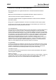
Chapter8 Waveforms PC MODE(1366X768 60HZ) CH1 H-sync (L21); CH2 V-sync (L22) CH1 GREEN (FB27) CONFIDENTIAL – DO NOT COPY Page 8-1 File No.
CH1 GREEN+(C294) CH1 GREEN # (FB27); CH2 VGAVSYNC (L22) CONFIDENTIAL – DO NOT COPY Page 8-2 File No.
CH1 VGAL (R193); CH2 AVOL (R194) CH1 PC_L (CE70+) ; PC_L (CE70-) CONFIDENTIAL – DO NOT COPY Page 8-3 File No.
AV&TV MODE (AV1/AV2/TV) VIDEO CH1 CVBS2 (R169); CH2 AV2CVBS (C255) CH1 AV2L (R237); CH2 AV2L (U22 PIN14) CONFIDENTIAL – DO NOT COPY Page 8-4 File No.
CH1 AV_L (U22 PIN13) ; CH2 AV_L (CE71-) CH1 AUSPL (R302);CH2 OUT2+5(J4 PIN4) CONFIDENTIAL – DO NOT COPY Page 8-5 File No.
CH1 DACBCLK (U23 PIN4); CH1 DACMCLK (U23 PIN5); CONFIDENTIAL – DO NOT COPY Page 8-6 File No.
CH1 DACLRCK (U23 PIN7) COMPONENT MODE (COMPONENT 1/2) CH1 COM_Y2 (L16); CH2 AVY1P (C269) CONFIDENTIAL – DO NOT COPY Page 8-7 File No.
CH1YCBCR_L2(L19) CH2 2A33 (U22 PIN11) CH1 AV_L (CE71+);CH2 AUSPL (R304) CONFIDENTIAL – DO NOT COPY Page 8-8 File No.
HDMI 1&2 CH1 RX1_2 (P11 PIN 1); CH2 DATA2+ (U31 PIN3) CH1 HDMIMCLK (U19 PIN 79) ;CH2 HDMIBCLK (U19 PIN 76) CONFIDENTIAL – DO NOT COPY Page 8-9 File No.
CH1 SOG_IN (U19 PIN4) CH1 HDMILRCK (U19 PIN75) CH2 HDMISDO (U19 PIN74) CONFIDENTIAL – DO NOT COPY Page 8-10 File No.
CH1 DDC_SDA (Q14 PIN3);CH2 DDC_SCL (Q13 PIN3) DTV HD CH1 VOB0 (RP35) CONFIDENTIAL – DO NOT COPY Page 8-11 File No.
CH1 AO1MCLK (DU9 PIN J1 ) CH2 AO1BCK (DU9 PIN J2) CH1 VOHSYNC (DU9 PIN V4) CONFIDENTIAL – DO NOT COPY Page 8-12 File No.
CH1 VOVSYNC (DU9 PIN W1) CH1 VODE (DU9 PIN W2) CONFIDENTIAL – DO NOT COPY Page 8-13 File No.
CH1 VOPCLK (DU9 PIN V3) CONFIDENTIAL – DO NOT COPY Page 8-14 File No.
Chapter 9 Trouble shooting MONITOR DISPLAY NOTHING (PC MODE) Start N0 LED is lighted 1. 2. 3. 4. Is Power board output +5V? Is J7 connector good? Is DC-DC OK? Is U6&U4 (3.3V) working ok? Yes N0 LED is lighting? It is in power saving 1. Check video cable 2. Is the timing supported? 3. Check sync input 4. Check VGASOG rout if analog (SOG) Yes N0 Is backlight on? 1.Check J7 PIN 14 2.Is inverter ok? 3.Is Power Board ok? Yes Yes N0 U11 no data out? It means data to LVDS 1.
(TV, COMPOSITE VIDEO1, 2, S-VIDEO) IS NOT DISPLAY CORRECTLY Start N0 1.Check video 2.Check DVD player Input signal good? Yes N0 U11 input correct? 1.Check P2&P12 signal 2.Check signal between P2 and U11 (IF AV1/AV2 mode) 3.Check Tuner &U11 (IF TV mode) 4.Check P12 (IF S-Video) 5.Check U11 POWER +3.3V 6.Check Y1 is OK? Yes N0 1.Check signal between U20 and U9 U11 output correct? Yes N0 LVDS output correct? 1.Check LVDS LINE 2.Check U11 clock (27MHz) 3.Check U11 power Yes 1.
(COMPONENT1, 2) IS NOT DISPLAY CORRECTLY Start N0 1.Check video 2.Check host’s setting Input signal good? Yes N0 1.Check signal between P4 2.Check power 12V& 5v P4 input correct? Yes N0 1.Check signal between U11&P4 2.Check U11 Clock (27MHZ) U11 input correct? Yes N0 LVDS output correct ? 1.Check U11 2.Check U11 power 3.3V&1.25v&1.8v Yes 1.Is J5 connected good? 2.Is panel working ok? END CONFIDENTIAL – DO NOT COPY Page 9-3 File No.
(HDMI) IS NOT DISPLAY CORRECTLY Start N0 1.Check video 2.Check host’s setting Input signal good? Yes N0 1.Check p10&p11 connect 2.Check signal between U31 and U19 U31 input correct? Yes N0 U11 no data out ? 1.Check U11 power 2.Check between signal U19 and U11 3.Check U19 clock 27MHZ Yes 1.Is J6 connected good? 2.Is panel working ok? END CONFIDENTIAL – DO NOT COPY Page 9-4 File No.
TROUBLE OF DC-DC CONVERTER Start N0 J7 PIN10,11,12 The voltage is about + 5V 1.Check power board 2.Check power cable connection J7 Yes N0 The voltage is about + 12V while power switch on 1.J7 connection good 2.Check J7 Pin1 is up to 3V? 3.Check power board J7 PIN 2,3,4 Yes N0 U1 pin 5 6 7 8 The voltage is about +5V while power switch on 1.J1 connection good 2. Check U11 GPIO_7 Pin Yes N0 The voltage is about +3.3V 1.J1 to connection good? 2.
TROUBLE OF DDC READING Start N0 Support DDC1/2B 1.Analog cable ok? 2.Check signal (U20 to P3) 3.Check U20 Voltage 4.Is compliant protocol? Analog DDC OK? Yes N0 HDMIDDC OK? Support DDC1/2B 1.Analog cable ok? 2.Check signal (U32 to P10) 3. Check signal (U34 to P11) 4.Is compliant protocol? Yes END CONFIDENTIAL – DO NOT COPY Page 9-6 File No.
Chapter 10 Block Diagram System Block Diagram 42” WXGA panel Digital Video bus AC IN Power Board Speakers J6 j5 J7 J4 Main Board □□□□□ Keypad/IR Board DTU1 DP1 P8 P11 P10 P9 P3 P6 P4 RF SPDIF RJ11 HDMI1 HDMI2 RCAX2 VGA PHONE YPbPr P5 P12 P2 P13 RCA S-video AV RCA OUT The TV system block diagram is powered by power board that transforms AC source of 100V~240V AC +/- 10% @ 50/60 HZ into DC 5V & 12V& 24Vsource.
The purpose is process the input audio signal to control volume, bass, treble, surround, and balance. The HDMI video and audio is must transmitting to MT8293 processed then TMDS signal to the MTK8202 generates the vertical and horizontal timing signals for display device. All functions are controllable by the main board. Plus, all functions in the IC boards are programmable using I2C Bus. CONFIDENTIAL – DO NOT COPY Page 10-2 File No.
Main Board Block Diagram CONFIDENTIAL – DO NOT COPY Page 10-3 File No.