
Service manual
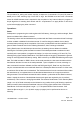

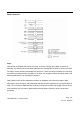
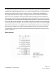
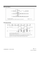
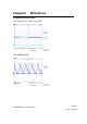
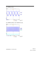
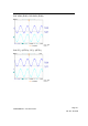
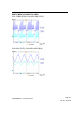
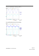
Table Of Contents
- VIZIO L42HDTV10A,GV42L_HDTV Service Manual
- 01-FEATURES
- 02-SPECIFITION
- 03-ON SCREEN DISPLAY
- 04-FACTORY PRESET TIMINGS
- 05-PIN ASSIGNMENT
- 06-MAIN BOARD I/O CONNECTIONS
- 07-THEORY OF CIRCUIT OPERATION
- 08-WAVEFORMS
- 09-TROUBLE SHOOTING
- 10-BLOCK DIAGRAM
- 11-SPARE PATRS LIST
- 12-1COMPLETE PARTS LIST_FOR L42 HDTV10A
- 12-2COMPLETE PARTS LIST_FOR GV42L HDTV
- MAIN BOARD CIRCUIT DIAGRAM_FOR L42 HDTV10A
- MIAN BOARD CIRCUIT DIAGRAM_FOR GV42L HDTV
- MAIN BOARD PCB LAYOUT_FOR L42HDTV10A(LG/AUO)
- MAIN BOARD PCB LAYOUT_FOR GV42L HDTV_LG
- ASSEMBLY EXPLOSION DRAWING_FOR L42HDTV10A_AUO
- ASSEMBLY EXPLOSION DRAWING_FOR L42HDTV10A_LG
- ASSEMBLY EXPLOSION DRAWING_FOR GV42L HDTV_LG

CONFIDENTIAL – DO NOT COPY
Page 7-52
File No. SG-0198
The procedure for exiting self refresh requires a sequence of commands. CK (and CK) must be
stable prior to CKE returning high. Once CKE is high, the SDRAM must have NOP commands
issued for tXSNR because time is required for the completion of any internal refresh in progress. A
simple algorithm for meeting both refresh and DLL requirements is to apply NOPs for 200 clock
cycles before applying any other command.
Operations:
Reads
Subsequent to programming the mode register with CAS latency, burst type, and burst length, Read
bursts are initiated with a Read command.
The starting column and bank addresses are provided with the Read command and Auto Precharge
is either enabled or disabled for that burst access. If Auto Precharge is enabled, the row that is
accessed starts precharge at the completion of the burst, provided tRAS has been satisfied. For the
generic Read commands used in the following illustrations, Auto Precharge is disabled.
During Read bursts, the valid data-out element from the starting column address is available
following the CAS latency after the Read command. Each subsequent data-out element is valid
nominally at the next positive or negative clock edge (i.e. at the next crossing of CK and CK). The
following timing figure entitled “Read Burst: CAS Latencies (Burst Length=4)” illustrates the general
timing for each supported CAS latency setting. DQS is driven by the DDR SDRAM along with output
data. The initial low state on DQS is known as the read preamble; the low state coincident with the
last data-out element is known as the read postamble . Upon completion of a burst, assuming no
other commands have been initiated, the DQs and DQS goes High-Z. Data from any Read burst
may be concatenated with or truncated with data from a subsequent Read command. In either case,
a continuous flow of data can be maintained. The first data element from the new burst follows either
the last element of a completed burst or the last desired data element of a longer burst which is
being truncated. The new Read command should be issued x cycles after the first Read command,
where x equals the number of desired data element pairs (pairs are required by the 2n prefetch
architecture). This is shown in timing figure entitled “Consecutive Read Bursts: CAS Latencies (Burst
Length =4 or 8)”.A Read command can be initiated on any positive clock cycle following a previous
Read command. Nonconsecutive Read data is shown in timing figure entitled “Non-Consecutive
Read Bursts: CAS Latencies (Burst Length = 4)”. Full-speed Random Read Accesses: CAS
Latencies (Burst Length = 2, 4 or 8) within a page (or pages) can be performed as shown on
following: