WINE-MATE Cooling Unit Use & Care Manual VINO1500HZD VINO2500HZD VINO3500HZD VINO4500HZD VINO6500HZD VINO8500HZD Vinotemp International Corp. www.vinotemp.com www.winemate.
Important Safety Information • • • DO NOT PLUG IN UNTIL 24 HOURS AFTER DELIVERY. DO NOT USE A GROUND FAULT INTERRUPTER (GFI). A DEDICATED 20 OR 30 AMPCIRCUIT IS REQUIRED (1500-4500HZD OR 6500-8500HZD).
TABLE OF CONTENTS Features & Specifications.…………………….……………..3 Installation Instruction………………………………………..5 Temperature Control & Humidity Adjustment...………..13 Care Guide…………………………………………………….16 Troubleshooting……………………………………………..17 Wiring Diagram……………………………………….………20 Customer Support……………………………………………21 Warranty……………………………………………………….
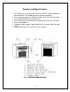
Features and Specifications • • • • • HZD cooling unit is designed and used to provide a stable temperature between 50~65 °F for suitable space at a normal environment. The refrigerated space will maintain humidity of 50~70% RH even when the environment becomes dry and humid. These temperatures and humilities are optimized for long term storage of wine, fur and tobacco. Horizontal cold-air supply is optimized for use in the wide cabinets or wine rooms.
Fig. 1.2 DIMENSIONS The dimension and capacity are specified as follows: MODEL CFM VINO-1500HZD VINO-2500HZD VINO-3500HZD VINO-4500HZD VINO-6500HZD VINO-8500HZD 120 180 250 250 500 500 CAPACITY cu ft (55°F/75°F) 90 200 650 1000 1500 2000 DIMENSIONS W”XD”XH” 14.25X16X13.25 14.25X16X13.25 14.25X21.25 X19.75 14.25X21.25 X19.
Installation Instruction Select a place to mount the unit where the exhaust airflow is unobstructed for a minimum of 6 inch. The area into which the unit exhausts must be well ventilated. If it is not, heat exhausted by the unit will build up and the unit will not operate properly. The ambient temperatures shall not be higher than 78°F for a VINO1500HZD unit and 95°F for the other units or lower than 50 °F. Additionally, cold supply air from the front grille must remain unobstructed.
• • • • • • If top exhaust, place another gaskets along the top exhaust at the top of the cooling unit (see Fig.2.3). Move the cooling unit towards the mounting sides and push to press the gaskets (see Fig 2.5). Fasten the 2 brackets and use 7/16” wrench to tighten the two ¼” screws (see Fig 2.6). Attach the exhaust and fresh air grille from the rear side of the cellar (see Fig 2.7). Plug the cooling unit in receptacle. Plug the wine cellar. Fig. 2.
Fig. 2.2 GASKET Fig. 2.
Fig. 2.4 THREAD INSERT Fig. 2.
Fig. 2.
Fig. 2.7 CABINET GRILLE 2. VINO3500-8500HZD THROUGH WALL INSTALLATION • Cut a rectangular opening at the wine room wall as illustrated. The dimensions of the opening shall be 1/4” larger than the width and height of the unit. • If top exhaust, cut another rectangular opening at the top of the cabinet to the length and width of the top exhaust. • Construct a shelf as shown. The shelf must be capable of supporting the weight of the unit.
• • Attach the molding to the wall not the unit. Plug the unit into a properly grounded and dedicated outlet of adequate capacity. Fig. 2.8 THROUGH WALL INSTALLATION Fig. 2.
3. Cellar Construction This is only a guide and shall be considered as minimum requirements. All interior walls and floors shall have a vapor barrier and a minimum of R11 insulation. All exterior walls and ceiling shall have a vapor barrier and a minimum of R19 insulation. The vapor barrier shall be installed on the warm side of the insulation.
Temperature Control & Humidity Adjustment 1. Temperature Setting • • • Set the temperature at 55 °F for the optimum aging of wine On initial start-up, the time required to reach the desired temperature will vary, depending on the quantity of bottles, temperature setting and surrounding temperature. Allow 24 hours to stabilize the temperature for each new temperature setting operation 2. Use of the controller Fig. 3.
2.1 LED Functions LED MODE ON Flashing ON ON Flashing ON ON Flashing FUNCTION Compressor enabled Anti-short cycle enabled Defrost cycle enabled Fan enabled Fan delay after defrost enabled Alarm occurring Temperature measuring unit Programming mode 3) Alarm Signals 3.
5) Parameter Programming 1. Press the SET + keys for 3 sec until the “°C” or “°F” LED starts blinking, then release the keys. 2. Press again the SET + keys for more than 7sec until the Pr2 label will be displayed, then release the keys. The first parameter Hy will be displayed. 3. Press up/down keys / to select the required parameter within 10 sec. 4. Press the “SET” key to display its value. 5. Use up/down keys to change its value within 10 sec. 6. Press “SET” to store the new value. 7.
Care Guide 1. Coil Cleaning • • • • • Clean the condenser coil regularly. Coil may need to be cleaned at least every 6 months. Coil is on the ambient air intake side of the cooling unit. Unplug the unit or disconnect power. Use a condenser brush or a vacuum cleaner with an extended attachment to clean the coil when it is dusty or dirty. Plug the cooling unit or reconnect power. 2. Moisture Removing • Remove the extra condensate if it is accumulated in the wine cellar at high humidity condition. 3.
Troubleshooting This Troubleshooting Chart is not prepared to replace the training required for a professional refrigeration service person, not is it comprehensive Complaint 1. Unit not running 2. Cabinet temperature high, unit stopping and starting with short running time 3. Temperature high, compressor stopping and starting but very short running time 4. Temperature high or not cooling and running continually; “HA” alarm blinking and beeping Possible Causes Response a. Power cord unplugged b.
l. 5. Unit running too long Failed components l. a. Improper room insulation & seal b. Exhaust restricted c. Room too large d. Ambient temperature higher > 90°F e. Dirty Condenser f. Improper condenser air flow 6. Fan motor running but compressor not running a. Post-compressor fan running mode b. Incorrect power supply c. Incorrect or loose wirings d. Failed components e. Liquid refrigerant compressor in the Check compressor windings, start relay and overload protector a.
but temperature rising high a. Check for fans & CFM 11. Evaporator a. Evaporator air flow restriction b. Not stopping due to air leak, high b. Check for seal, door opening, freezing up ambient temperature or setting c. Bad thermostat or sensor d. Low ambient temperature low e. Moisture in the system f. Refrigerant low or leaking g. Capillary tube blockage 12. Water leak 13. Circuit tripping 14. Noisy operation ambient temperature and setting c. Check for thermostat and sensor d.
Wiring Diagram Fig. 6.1 VINO1500-2500HZD Wiring Diagram Fig. 6.
Customer Support If you still have problems, please contact us at: Vinotemp International 17631 South Susana Road Rancho Dominguez, CA 90221 Tel: (310) 886-3332 Fax: (310) 886-3310 Email: info@vinotemp.
Warranty Thank you for choosing a Vinotemp cooling unit. Please enter the complete model and serial numbers in the space provided: Model_________________________________________________________ Serial No.______________________________________________________ Attach your purchase receipt to this owner’s manual. 1. Limited Warranty VINOTEMP warrants its products to be free from defects due to workmanship or materials under normal use and service, for twelve months after the initial sale.
is determined to be faulty and is within the twelve month warranty period VINOTEMP will, at its discretion, repair or replace the unit and return it free of charge to the original retail customer. If the unit is found to be in good working order, or beyond the initial twelve month period, it will be returned freight collect. 2. Limitation of Implied Warranty VINOTEMP’S SOLE LIABILITY FOR ANY DEFECTIVE PRODUCT IS LIMITED TO, AT OUR OPTION, REPAIRING OR REPLACING OF UNIT.