
Unit installation


- 5 -
Installation Instruction
1. Cabinet Location
• Place the wine cabinet in a properly ventilated location. Otherwise, heat
exhausted by the cooling unit will build up and it will not operate properly.
• The exhaust area must not be a closed space and must be ventilated. The
ambient temperatures shall not be higher than 90 °F or lower than 50 °F.
1) Rear Exhaust Location
• Leave min 6 “clearance from the rear to the wall.
• Leave min 12” clearance from the top to the ceiling.
• Leave min 6” clearance from the left and right sides.
2) Front Exhaust Location
• Leave min 6” clearance from the front if left and right sides unobstructed.
• Or, leave min 36” clearance from the front if left and right sides obstructed
3) Top Exhaust Location
• Leave min 12” from the top to the ceiling.
• Leave min 2 “clearance from the rear to the wall.
• Leave min 2” clearance from the left and right sides.
4) Side Exhaust Location
• Leave min 6 “clearance from the left or right side to the wall.
• Leave min 12” clearance from the top to the ceiling.
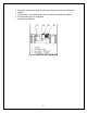
2. Cooling Unit Installation
• The cooling unit produces cooling supplied into the cabinet, and it also
generates heat that must be exhausted outside the cabinet. So the supply
side and exhaust side must be separated and sealed (see Fig. 2.1).
• Cut a rectangular inside opening at the rear of the cabinet with the 1/4”
clearance inwards to the width and height of the cooling unit. By not going
through, leave 1/2” lip inside at the wall to place the gaskets (see Fig. 2.2).
• If top exhaust, cut another rectangular opening at the top of the cabinet to
the length and width of the top exhaust (see Fig.2.2).
• Make 2 holes at the ceiling to install the 1/4 inside diameter wood thread
inserts (see Fig.2.2).
• Place the gaskets (1/2” foam tape)on the gasket lips (see Fig 2.1).
• If top exhaust, place another gaskets along the top exhaust at the top of
the cooling unit (see Fig.2.3).
• Move the cooling unit towards the mounting sides and push to press the
gaskets.
• Fasten the 2 brackets and use 7/16” wrench to tighten the two ¼” screws
(see Fig 2.1).