Gas Controls Technical Reference Manual Part # GCTRM Rev 3 (12/10/09) © 2006 Garland Commercial Industries, Inc.
Page 2 Part # GCTRM Rev 3 (12/10/09)
Garland & US Range Technical Reference Manual Table Of Contents Section Section 1 Page Model Number Identification . . . . . . . . . . . . . . . . . . . . . . . . . . . . . . . . . . . . . . . . . . . 5 General Information All Models . . . . . . . . . . . . . . . . . . . . . . . . . . . . . . . . . . . . . . . . . . . . . . . . . . . . . . . . . 6 Garland G Series Restaurant Ranges(2007 – Sit Control) . . . . . . . . . . . . . . . . . . . . . . . . . . . . . . . .
Page 4 Part # GCTRM Rev 3 (12/10/09)
Section 1 Model Number Identification Part # GCTRM Rev 3 (12/10/09) Page 5
General Information All Models • All equipment is supplied with 6” (152mm) legs unless specified • In the Commonwealth of Massachusetts this product must be installed by a licensed plumber or gas fitter.
Base Model Designations & Total Input Rates Input BTU/Hr Model # Description Natural Gas Propane Gas G24-4S 24” (610mm) nominal size unit, 4 open burners, storage base 132,000 104,000 G24-4L 24” (610mm) nominal size unit, 4 open burners, space saver oven 164,000 132,000 G36-6S 36” (914mm) nominal size unit, 6 open burners, storage base 198,000 156,000 G36-6R 36” (914mm) nominal size unit, 6 open burners, standard oven 236,000 188,000 G36-6C 36” (914mm) nominal size unit, 6 open burners,
US Range U Series Restaurant Ranges (2007 – Sit Control) Clearances Clearances Applicable For All Models Surface Sides Rear Combustible Wall Minimum 12” (305mm) 6” (152mm) Non-Combustible Wall Minimum 0” 0” Gas Pressures Gas Minimum Supply Pressure Manifold Operating Pressure Natural 7” WC (17.5 mbar) 4.5” WC (11.
Base Model Designations & Total Input Rates Input BTU/Hr Model # Description Natural Gas Propane Gas U24-4S 24” (610mm) nominal size unit, 4 open burners, storage base 128,000 104,000 U24-4L 24” (610mm) nominal size unit, 4 open burners, space saver oven 160,000 132,000 U36-6S 36” (914mm) nominal size unit, 6 open burners, storage base 192,000 156,000 U36-6R 36” (914mm) nominal size unit, 6 open burners, standard oven 230,000 188,000 U36-6C 36” (914mm) nominal size unit, 6 open burners,
Sunfire X Series Restaurant Ranges (2007 – Sit Control) Clearances Clearances Applicable For All Models Surface Sides Rear Combustible Wall Minimum 12” (305mm) 6” (152mm) Non-Combustible Wall Minimum 0” 0” Gas Pressures Gas Minimum Supply Pressure Manifold Operating Pressure Natural 7” WC (17.5 mbar) 4.5” WC (11.
Individual Burner Input Rates Input BTU/HR Burner Natural Gas Propane Gas Open Top 30,000 26,000 Hot Top Burner (In lieu of 2 open top burners) 20,000 19,000 Griddle Burner (In lieu of 2 open top burners) 20,000 19,000 Raised Griddle Broiler (Consists of 3 burners) 33,000 33,000 Oven Burner Standard 33,000 29,000 Space Saver Oven 25,000 25,000 Rates are for installations up to 2000’ (610m) above sea level Base Model Designations & Total Input Rates Input BTU/Hr Model # Description Na
Garland Restaurant Series Top Section 2 x 12” Sections 24” Wide 3 x 12” Sections 36” Wide 4 x 12” Sections 48” Wide 5 x 12” Sections 60” Wide 24” Raised Griddle/Broiler 60” Wide 6 Burner 36” Raised Griddle/Broiler 60” Wide 4 Burner 6 x 12” Sections 72” Wide 12 Burner 4 Burner 30” Wide Minimum Supply Pressure:: Page 12 Base (1) Space Saver Oven G28, H28, P28 (1) Storage Base G28S, H28S, P28S (1) Standard Oven (1) Range Base Convection Oven (1) Storage Base (2) Space Saver Ovens (1) Std.
Garland Heavy Duty Master Series Model Numbers Prefix Definitions M MS MST Master E Master Sentry c/w open top pilot shut off Master Sentry Cc/s total flame failure Model M,MS, MST42R(E) M,MS, MST42RC(E) M,MS, MST42S(E) M,MS, MST42T(E) M,MS, MST43R(E) M,MS, MST43RC(E) M,MS, MST43S(E) M,MS, MST43T(E) M,MS,MST44R(E) M,MS,MST44RC(E) M,MS,MST44S(E) M,MS,MST44T(E) M,MS,MST45R(E) M,MS,MST45RC(E) M,MS,MST45S(E) M,MS,MST45T(E) M,MS,MST46R(E) M,MS,MST46RC(E) M,MS,MST46S(E) M,MS,MST46T(E) M,MS,MST47R(E) M,MS,MST4
Model M,MS,MST24B(E) M,MS,MST34B(E) M35 M70 Width 24 34 17 24 Description 24” wide char-broiler 34” wide char-broiler Deep fat fryer Deep fat fryer Minimum Supply Pressure: NAT – 7” WC Manifold Operating Pressure: NAT – 6” WC PRO – 11” WC PRO 10” WC Garland 40 Series Heavy Duty R RC S SD T FT G GTH Suffix Definitions Standard oven base Convection oven base Storage base Storage base with doors Modular top/Table top Front open burner, rear hot top Griddle Thermostatically controlled griddle Model 42-
Part # GCTRM Rev 3 (12/10/09) G - Manual TG - Thermostat control BG - Broiler/griddle combination Griddle 2 - 2 open top burners 4 - 4 open top burners etc.
Page 16 French Top Spectro Heat Burner Even Heat Hot Top Burner Open Top Burner (2 Burners) NAT – 7” WC NAT – 6” WC 28,000 BTU/Hr 15,000 BTU/Hr Propane Gas 35,000 BTU/Hr 37,000 BTU/Hr 28,000 BTU/Hr 25,000 BTU/Hr 35,500 BTU/Hr Supply Pressure Natural Gas 40,000 BTU/Hr 37,000 BTU/Hr 30,000 BTU/Hr 25,000 BTU/Hr 35,500 BTU/Hr 12,500 BTU/Hr 30,000 BTU/Hr 15,000 BTU/Hr 1 Section 1 Section 1 Section 1 Section 1 Section 1 Section 18” Fry Top 24” Fry Top 36” Fry Top Griddle Griddle Griddle Operating Pr
Section 2 Serial Number Identification Part # GCTRM Rev 3 (12/10/09) Page 17
Serial Number Identification Serial numbers are useful in determining the age of the equipment and if it is under warranty. In some cases, the serial number is describes as a code or W/N for warranty number.
S/N 9301PC0001 93 = Year Built 01 = Month Built PC = Product Code 0001 = Sequential number of unit built that month In some cases, you will find the serial number ending with an R, i.e. 9904RG002R. This indicated that the unit was built in our Mississauga Plant. The R was removed in 2002 and switched to the 4 digits after the product code. In table 3, you will find a listing of Garland product codes.
Page 20 Part # GCTRM Rev 3 (12/10/09)
Section 3 Certification Markings Part # GCTRM Rev 3 (12/10/09) Page 21
Certification Markings There are many marks used on equipment manufactured and distributed by Garland. Below is a summary of what the marks are and where they are used. Electric Cooking Equipment Sanitation Mark EPH All equipment sold in the USA requires a mark to show that is complies with ANSI/NSF Standards 2 & 4.
Gas Cooking Equipment TM UL Gas-Fired – Some gas equipment manufactured by GCI bears the UL GAS-FIRED mark. There are three types of mark, UL, CUL and CULUS; the marks are for the US, Canada and, Canada/US respectively. Equipment bearing this mark is certified to the harmonized ANSI Z83.11/CGA 1.8 standard. Note: when you look at all the marks used in the Garland group, you will notice that GCR uses only CSA and GCI uses predominantly UL. The reason for this comes down to two reasons. 1.
Page 24 Part # GCTRM Rev 3 (12/10/09)
Section 4 Properties And Characteristics of Fuel Gases Part # GCTRM Rev 3 (12/10/09) Page 25
Properties And Characteristics Of Fuel Gases The petroleum gases most commonly used in the gas industry are natural gas and it two processed derivatives, propane and butane. The two most commonly used fuels in commercial cooking equipment are natural gas and propane. The major ingredient in fuel gas in methane. Expansion Factors Natural Gas Your propane tank at home is usually only filled to 80% of its capacity to allow for expansion.
Section 5 Operation Of Controls Part # GCTRM Rev 3 (12/10/09) Page 27
Operation Of Controls CAUTION: Gas will flow to top burners even with the top pilots out. Gas will not be interrupted. It is the responsibility of the operator to check the ignition of the burners. SHOULD IGNITION FAIL AFTER 10 SECONDS, TURN THE BURNER VALVE OFF AND WAIT 5 MINUTES AND TRY AGAIN. Open Top Burners All models where applicable, i.e H286, 43-40R, 44-40RC. 1. Remove top grates and ring grates. 2. Check flash tubes to see that they are properly positioned on burner change ports.
Standard Oven 3. Repeat lighting instructions in section “A” above. Lighting G, U, X Restaurant Ranges (Sit Control) 1 Remove oven buttons. Lighting 2. Depress and hold the reset button (Red) located at the lower front of the oven (beneath the oven door) while lighting the oven pilot. Continue to depress the rest button for 60 seconds. Release the button, if the pilot does not stay lit, repeat this procedure after 5 minutes 1. Push in the SIT control knob.
5. To shut the pilot completely off, extinguish the pilot flame. The internal pilot valve will automatically close within 60 seconds. Each time this is done, the pilot will have to be re-lit. 2. Using the access hole located below the louver in the panel, push the RED IGNITOR BUTTON continuously until the oven pilot ignites. (See Prior) NOTE: This procedure is the same for the convection models with SIT controls.
Section 6 Gas Valves And Adjustments Part # GCTRM Rev 3 (12/10/09) Page 31
Gas Valves And Adjustments Pilot Adjustment Valves SINGLE PILOT VALVE • Also known as gum valves. • Available in single or double. • Double contains adjustment for an open top burner and oven. • Adjustable with a set-screw. • Turn set-screw counter-clockwise to increase flow. • Turn set-screw clockwise to decrease flow.
Oven Pilot Oven pilots should reach and engulf the tip of the thermocouple as illustrated below. If the pilot flame fully engulfs the thermocouple premature failure will occur. Oven Pilot 3/8" TO 1/2" Reminder! Adjustments on valves are for the low flames setting only. Full Range Non-Adjustable Control • Used to control the flow of gas for the oven, • Used together with the oven thermostat. • Used fully open or fully closed (no medium setting). • No adjustments or calibrations.
The valve itself allows you to bypass the plunger by pushing it in. This allows gas flow to the pilot, which then must be ignited. The valve must be held depressed for approximately 30 seconds in order to sufficiently heat the thermocouple and generate millivoltage. If the valve is not depressed for 30 seconds it shuts down the gas flow. Open (Star) burner 1/2” stable, sharp inner blue cones.
Oven burners, Knuckle burners If the burner flames are soft and unstable or show yellow tipping increase the amount of air by opening the air shutter. 4” to 6” stable, blue flame, with slight yellow tips. 4" to 6" Blue Flame Oven H Burner - Side View 7/16" Air Shutter Knuckle Burner Side View Hood Air Shutter Note: If the burner flames are sharp, but lift off the burner ports, reduce the amount of primary air by closing the air shutter.
Page 36 Part # GCTRM Rev 3 (12/10/09)
Section 7 Adjustments, Removal, Replacement, And Calibration Of Controls Part # GCTRM Rev 3 (12/10/09) Page 37
630 Euro Sit Control The 630 EUROSIT is a multifunction single knob valve with combined modulating/snap thermostat control. Pilot gas flow adjustment SIT Control Snap and Modulating gas valve Thermoelectric Flame Failure Device Dual Main Gas Inlet and Outlet Two Mount Options Thermoelectic Pilot Safety Valve Thermocouple Connection Thermostatic bellows Gas Outlet Pressure Test Pilot Gas Outlet Gas Inlet Pressure Test The gas inlet and outlet test points should not be used.
Sit Control Griddle SIT Control P/N 4523007 Shorter Thermocouple No Heat Cover Temperature Control Range 176°F – 600°F (80°C – 320°C) Removal And Replacement Oven SIT Controll P/N Oven – 4523006 59” Thermocouple Temperature Control Range 212°F – 644°F (100°C – 340°C) Thermostat Replacement 1. Remove left and middle grates. 2. Remove grate support gas line cover 3. Remove gas line shield 4. Remove Grease crumb tray 5. Remove left column trim piece (3 screws), then push down and pull off. 6.
11 Install the new thermocouple using the above procedure, but in reverse. Bulb Tip Holder Thermostat Replacement: 1. Unmount the oven thermostat capillary from its holder. 2. Carefully snake the capillary through the guide holes and out of the guard holder.
3. Remove the gas lines from the valve. You will also need to remove the fittings from the valve. 4. Remove the two nuts and bolts that hold the thermostat in place. (Do not lose) C. Observe capillary and T couple routing 5. Remove the thermostat To install a new thermostat: 1. Ensure that the fittings removed from the housing are installed in the same location where they were found on the control that is being replaced 2.
D. Insure that the temperature bulb is secured in the capillary guard holder as shown: 3. Check for leaks 4. Perform an operational check of the new control using your pyrometer as a crosscheck. Temperature recovery should be most responsive when initial temperature setting is set to 400 ° F. Temperature swings of ± 30 ° F at this temperature should be no longer than thirty minutes when heating a cool unit.
NOTE: A replacement thermostat will come with the by-pass in the closed position. CALIBRATION SCREW BY-PASS ADJUSTMENT SCREW The control should be re-calibrated if your reading is not within ± 20° F of the dial setting (350°F). If re-calibration is required, the additional steps that need to be taken are as follows: 5. Hold the dial firmly, insert a screwdriver through the center of the dial and push the calibration stem. Do Not turn this stem. 6.
Heavy Duty FDO Control Thermostat 1. With the oven cold, turn the dial counter-clockwise slowly from “Low Stop”, until the bypass seat just snaps on. 2. Remove the dial. 3. With a screw driver, turn the bypass flame adjuster screw counter-clockwise to increase the bypass flame or clockwise to decrease the entire flame to a minimum stable flame. The FD Control is a heavy duty, high capacity gas thermostat. It is a modulating snap by-pass. Garland uses the FD Control for range ovens and Pizza decks.
4. Allow the oven, or appliance, to heat and the thermostat to cycle three times. After sufficient time, check the temperature, if the temperature does not read with in ±20° of the dial setting, re-calibrate as follows: 5. Pull the dial straight off without turning the thermostat shaft. 6. Hold the calibration plate and loosen the two calibration screws until the plate can be moved independently of the control. 7.
1. Turn all griddle temperature control dials to 350°F (177°C). In order to allow the temperature to stabilize, the controls must be allowed to cycle three times before taking a test reading. 2. Check the temperature reading when the control cuts down to by-pass by placing the sensor firmly on the griddle surfaces directly above the sensing bulb of the control. Reading of the test instrument should be between 335°F (168°C) and 365°F (185°C). 3.
4. Carefully remove the thermostat dial, not disturbing the dial setting. 5. Hold the thermostat shaft steady and with a small flat blade screw driver, turn the calibration screw located inside the shaft clockwise to decrease the temperature or counter-clockwise to increase the temperature. Note each 1/4 turn of the screw will create a change of approximately 25°F. 6. Replace the thermostat dial and repeat steps 1 through 3 to verify that the correct adjustment has been made. Griddle thermostat 1.
Page 48 Part # GCTRM Rev 3 (12/10/09)
Section 8 Gas Pressure Regulators Part # GCTRM Rev 3 (12/10/09) Page 49
Gas Pressure Regulators Purpose Of A Gas Pressure Regulator Hydrostatic Relief Device Gas pressure regulators have two main purposes, to reduce supply main pressure to safe operating pressures of connected appliances and to maintain constant downstream pressure, regardless of changes in the gas flow or upstream pressure variations. A hydrostatic relief device is used in propane systems. They are to be installed between two valves in a propane system.
The Restricting Element moves in response to the measuring element when the downstream pressure changes. Usually, it is a disk or plug that controls the amount of flow by varying the orifice opening. The Atmospheric Vent allows the air above the diaphragm to escape or enter as the diaphragm moves up or down. Vent Limiting Orifice is used in appliance regulators. It allows equal limits of inhalations and escape of air from the upper diaphragm chamber.
Page 52 Part # GCTRM Rev 3 (12/10/09)
Section 9 Thermocouples And How They Work Part # GCTRM Rev 3 (12/10/09) Page 53
Thermocouples And How They Work Thermocouples are used to generate voltage to hold a magnet on a pilot safety valve. It plays an important part of the flame safety system in a gas oven. The thermocouple uses the combined effects of temperature change and electricity. It consists of a bimetallic strip joined at one end (called the hot junction). When the hot junction is heated, a DC voltage is generated across the two other ends of the strips (the cold junction).
Section 10 Trouble Shooting The Oven Pilot Safety System Part # GCTRM Rev 3 (12/10/09) Page 55
Trouble Shooting The Oven Pilot Safety System Automatic Pilot Valve The automatic pilot valve is a protective device that allows gas to flow to the oven burner only when the pilot burner is burning. (This is used on GARLAND ovens and ranges to have safe lighting provisions provided by the flow interrupter that will not allow gas to flow to the oven burner while the red button is depressed.) GARLAND has used two different types of pilot safety valves.
Figure B 3/8" TO 1/2" Pilot Thermocouple If, while following the proper lighting procedures, the magnet cannot be made to “HOLD”, inspect the pilot flame for proper size and adjustment (see pilot burner adjustment). If the magnet will still not hold, make the following checks. Closed Circuit Test (To test magnet & thermocouple as a complete unit) To make the closed circuit test, remove the thermocouple lead from the magnet contact.
Open Circuit Test 1. Disconnect the thermocouple from the safety valve. 2. Attach the thermocouple to the millivolt test instrument. 3. Heat the sensor end of the thermocouple at the pilot flame or similar flame characteristics, monitoring the millivolt meter. 4 If the millivolt reading is below 14 millivolts, replace the thermocouple. NOTE: The Sit thermocouple open circuit voltage will be approximately 18-28 millivolts. 5.
Section 11 Gas Equipment Field Service Trouble Shooting Guide Part # GCTRM Rev 3 (12/10/09) Page 59
Gas Equipment Field Service Troubleshooting Guide A professional as listed in your maintenance and repair center guide should perform service. PROBLEM POSSIBLE CAUSE SOLUTION Burner flame soft-lazy tip yellow. Not enough air mixing with gas. Open air shutter. Flame lifts off burner ports. Flashes back in Burner. Pops excessively when turned off. To much air mixing with gas. Close air shutter. Delayed ignition. Unit over gassed or orificed incorrectly Check gas pressure and orifice size.
Section 12 Maintenance & Care Instructions For Ranges And Oven Surfaces Part # GCTRM Rev 3 (12/10/09) Page 61
Garland and US Range Operating, Maintenance and Care Instructions For Ranges and Oven Surfaces Exterior Cleaning Black Baked Enamel Griddle plates should be wiped daily while still warm. Remove carbonized grease or food with a spatula. When necessary, clean the griddle’s surface thoroughly using a fine griddle brick or a liquid griddle cleaner (available from your kitchen equipment dealer). Polish the griddle surface to a bright finish. Wash the griddles surface, rinse and dry thoroughly.
• Soiled and burnt deposits can be removed with a wire brush. Difficult to remove burnt on deposits can usually be removed using an oven cleaner. Wash, dry thoroughly, and then rub with vegetable oil. • Continuing this procedure will prohibit the development of rust and will eventually form a non-stick surface with the carmelization of oil on the cast iron top grates and rings. Porcelain Tops & Grates Top grates should be washed daily with a hot detergent or soap solution and dried thoroughly.
• To brand meat, place it on an unused heated area of the rack. • Delicate fish is best broiled in a pan or on a metal platter. Stock Pot Ranges Cast Iron Tops When cast iron tops (which are covered in grease) arrive at the end users, the following seasoning and care is recommended. • Wash top grates with hot mild detergent or soap solution. Dry thoroughly. Rub with vegetable oil on all exposed surfaces in the direction of the grain.
Section 13 Gas Technician’s Glossary Part # GCTRM Rev 3 (12/10/09) Page 65
Gas Technician’s Glossary Air-Gas Ratio: The ratio of combustion air supply flow rate to the fuel gas supply flow rate. Air Shutter: An Adjustable shutter on the primary air opening of a burner, which is used to control the amount of combustion air introduced into the burner body. Atmospheric Pressure: The pressure exerted upon the earth’s surface by the weight of atmosphere above it.
Flame Velocity: The speed at which a flame travels through a fuel-air-mixture. Burning speeds vary with types of gases, and the amount of air mixed with the gas. This air to gas ratio is very important in that it is directly related to flame stability Flashback: An undesirable flame characteristic in which burner flames strike back into a burner to burn there or to create a pop after the gas supply has been turned off.
Limits of Flammability: Upper and lower ranges of gas in the air-gas mixture that will support combustion. Low amount of fuel makes mixture lean. High amount of fuel renders mixture rich. Port: Any opening in a burner head through which gas or an air-gas mixture is discharged for ignition. Manifold: The conduit of an appliance, which supplies gas to the individual burners. Port Loading: The input rate of a gas burner per unit of port area, obtained by dividing input rate by total port area.
Updraft: Excessively low air pressure existing at the outlet of a chimney or stack which tends to increase the velocity and volume of gases passing up the stack. Utility Gases: Natural gas, manufactured gas, liquefied petroleum gas-air mixtures or mixtures of any of these gases. Vent: A device, such as a pipe, to transmit flue products from an appliance to the outdoors.
Page 70 Part # GCTRM Rev 3 (12/10/09)
Section 14 Range Wiring Diagrams Part # GCTRM Rev 3 (12/10/09) Page 71
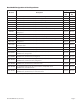
Garland and US Range Gas Ranges Wiring Diagrams Number N/A N/A 3056100 229064 2706601 2706602 2706603 4514771 4514772 4514774 2529700 2529701 2529600 2444200 2444300 4524261 4524262 4524263 4524800 4524801 4524802 Description Garland Restaurant Duty left RC Oven Garland Restaurant DUTY RC2 Oven US Range C836C Cuisine Series US Range 836C Cuisine Series US Range Px/S Series Left Single RC Oven US Range Px/S Series Right Single RC Oven US Range Px/S Series 2 RC Ovens US Range Px/SX Series Left Single RC Oven
Part # GCTRM Rev 3 (12/10/09) Door Switch Normally Closed Normally Open Common 16 16 11 Black Ground 14 30 Motor White 11 Black 13 Left "RC" Oven Section 120 Volts, 3.
Page 74 11 30 14 13 15 31 Common (Door Switch) Normally Open Ground Rocker Switch 25 16 29 28 27 White Black Right Motor "RC2" Wire Diagram 120 Vol, 6.
3056100 US Range C836C Cuisine Series Part # GCTRM Rev 3 (12/10/09) Page 75
229064 Page 76 US Range 836C Cuisine Series Part # GCTRM Rev 3 (12/10/09)
2706601 US Range Px/S Series Left Single RC Oven Part # GCTRM Rev 3 (12/10/09) Page 77
2706602 US Range Px/S Series Right Single RC Oven Page 78 Part # GCTRM Rev 3 (12/10/09)
2706603 US Range Px/S Series 2 RC Ovens Part # GCTRM Rev 3 (12/10/09) Page 79
4514771 US Range Px/SX Series Left Single RC Oven Page 80 Part # GCTRM Rev 3 (12/10/09)
4514772 US Range Px/SX Series Right Single RC Oven Part # GCTRM Rev 3 (12/10/09) Page 81
4514774 US Range Px/SX Series Two RC Ovens Page 82 Part # GCTRM Rev 3 (12/10/09)
2529700 ME/MSTE 40RC Electric Spark Part # GCTRM Rev 3 (12/10/09) Page 83
2529701 M/MS 40RC Page 84 Part # GCTRM Rev 3 (12/10/09)
2529600 M/MS 40 Electric Spark Part # GCTRM Rev 3 (12/10/09) Page 85
2444200 Sentry Electric Spark Page 86 Part # GCTRM Rev 3 (12/10/09)
2444300 STE286RC, STE284RC Left, ST283RCE Part # GCTRM Rev 3 (12/10/09) Page 87
Page 88 PART NUMBER ITEM DESCRIPTION WIRING DIAGRAM G, GF, U RT/SGL C 4524261 NC NO ORIENTATION SWITCH OVEN DOOR SWITCH FLEX CONDUIT 36" 26 NC NO 1 27c 30 BLK 28 27a 29 MOTOR WHT 11 COOK - COOL SWITCH 29 FLEX CONDUIT 15" 27b FLEX CONDUIT 36" GND 30 MODELS 28 SWITCH VIEWED FROM FRONT COOK OFF COOL BLACK OR BROWN ANG. ±2° (EXCEPT AS NOTED) APPR. DR. V.C. A.V. GARLAND COMMERCIAL RANGES LIMITED MISSISSAUGA, ONTARIO, CANADA DATE DEC 14/07 JAN.
Part # GCTRM Rev 3 (12/10/09) PART NUMBER ITEM DESCRIPTION 13 OVEN DOOR SWITCH WIRING DIAGRAM G, GF, U LT/SGL FLEX CONDUIT 66" 16 NO NC 4524262 31 MOTOR C 1 15c BLK WHT 14 15a 15c 11 COOK - COOL SWITCH 14 FLEX CONDUIT 45" 15a 15b GND 31 FLEX CONDUIT 36" 16 MODELS 13 SWITCH VIEWED FROM FRONT COOK OFF COOL BLACK OR BROWN ANG. ±2° (EXCEPT AS NOTED) APPR. A.V. DR. GARLAND COMMERCIAL RANGES LIMITED MISSISSAUGA, ONTARIO, CANADA DATE JAN.
Page 90 PART NUMBER ITEM NO NC 14 15a DESCRIPTION WIRING DIAGRAM G, GF, U 2 RC 13 OVEN DOOR SWITCH LEFT FLEX CONDUIT 66" 16 C 4524263 31 30 28 26 29 27a FLEX CONDUIT 36" OVEN DOOR SWITCH RIGHT 27c C 1 15c MOTOR WHT BLK LEFT RC OVEN SECTION BLK FLEX CONDUIT 15" MOTOR WHT 27b FLEX CONDUIT 45" 15c 11a 15a 15b COOK OFF COOL 13 28 ANG. ±2° (EXCEPT AS NOTED) APPR. A.V. DR. GARLAND COMMERCIAL RANGES LIMITED MISSISSAUGA, ONTARIO, CANADA DATE JAN.
Part # GCTRM Rev 3 (12/10/09) PART NUMBER ITEM DESCRIPTION WIRING DIAGRAM G,GF,U RGB RT REV 0 C 4524800 NC NO ORIENTATION SWITCH OVEN DOOR SWITCH FLEX CONDUIT 36" 26 NC NO 1 27c 30 BLK 28 27a 29 MOTOR WHT 11 COOK - COOL SWITCH 29 FLEX CONDUIT 15" 27b FLEX CONDUIT 36" GND 30 MODELS 28 SWITCH VIEWED FROM FRONT COOK OFF COOL V.C. TITLE: DR. : ±.031 TOLERANCES REV APPR. ANG. ±2° (EXCEPT AS NOTED) DESCRIPTION 120 VOLT INPUT 120 VOLTS DR.
Page 92 PART NUMBER ITEM FLEX CONDUIT 36" DESCRIPTION 13 OVEN DOOR SWITCH WIRING DIAGRAM G, GF, U RGB LT 16 NO NC 4524801 30 MOTOR C 1 15c BLK WHT 14 15a 15c 11 COOK - COOL SWITCH 14 FLEX CONDUIT 15" 15a 15b GND 30 FLEX CONDUIT 36" 16 MODELS 13 SWITCH VIEWED FROM FRONT COOK OFF COOL BLACK OR BROWN ANG. ±2° (EXCEPT AS NOTED) APPR. DR. GARLAND COMMERCIAL RANGES LIMITED MISSISSAUGA, ONTARIO, CANADA DATE 1 PHASE 1 OF 2 4524801 SHT APPR.
Part # GCTRM Rev 3 (12/10/09) PART NUMBER ITEM NO NC 14 15a DESCRIPTION WIRING DIAGRAM G/ GF RGB 2RC 13 OVEN DOOR SWITCH LEFT FLEX CONDUIT 36" 16 C 4524802 31 30 REV 0 28 26 29 27a FLEX CONDUIT 36" OVEN DOOR SWITCH RIGHT 27c C 1 15c MOTOR WHT BLK LEFT RC OVEN SECTION BLK FLEX CONDUIT 15" MOTOR WHT 27b FLEX CONDUIT 15" 15c 11a 15a 15b 16 COOK OFF COOL 13 28 ANG. ±2° (EXCEPT AS NOTED) APPR. DR.
30129 Sheet 2 of 3 Master Series Broiler/Range interconnection kit Page 94 Part # GCTRM Rev 3 (12/10/09)
30129 Sheet 3 of 3 Restaurant Series Broiler Range interconnection kit Part # GCTRM Rev 3 (12/10/09) Page 95
Page 96 G01475-1 G01477-3 TO SALAMANDER G01739-1 01918-5 01961-1 3013000 48" G01475-2 3013000 4524079 33" DESCRIPTION TUBING 3/4" x 78 1/2"LG X .
Section 15 Service Bulletins Part # GCTRM Rev 3 (12/10/09) Page 97
Total Pages 4 BULLETIN # B-54-2008-S From: Parts and Service Department To: All Authorized Service Agencies Date: June 18, 2008 Product: Garland G, U, and X Series Restaurant Range Models Subject: Sit Valve Introduction Please find the enclosed introduction to the Sit Valve Modulating/Snap Thermostat used in the Garland G, U, and X Series Restaurant Range Models.
Sit Valve Field Guide G, U, and X Series 1 2 A B When installing the knob, align the set screw (a) with the hole on the hub (b). 3 The tab must be intact on the knob for the knob to properly stop as shown in figure 2. If the tab is missing the knob will continue to turn until the pilots are extinguished. If the tab is damaged or missing, replace the knob.
5 6 A To adjust the pilot size, turn the pilot adjustment screw (A). The pilot flame should be approximately ¾ of an inch long. 7 No adjustment should be made to the screw circled above. Please see notes* 8 A B To shut down all gas to pilots and burners, loosen the knob set screw and gently pull knob off and proceed to figure 8. Page 100 With the knob removed, turn the hub until the metal tab (B) lines up with the * symbol (A).
* Notes: The Sit Thermostat used in the Garland G, U and X series is a Modulating/Snap thermostat with a multifunctional single knob. The part number for theOven Thermostat is 4523006 (Long Capillary) and the Griddle Thermostat is 4523007(Short Capillary). Before any calibration is attempted, the thermostat should be set at400°F and be allowed to cycle for a minimum of 30 minutes.
Page 1 of 2 BULLETIN # A-50-2009-S From: Parts and Service Department To: All US Authorized Service Agencies Date: April 6, 2009 Subject: SIT Control Operational Guide Models Affected: G, GF, U, and X Series Ranges Due to many questions regarding the operation of the SIT Control, below is a description of the valves operation for review. The SIT control is a Modulating Snap Combination Safety Valve and Thermostat Control.
Page 2 of 2 Garland uses a fixed drilled orifice to regulate the first stage in the SIT Control as shown below. Orifice (Internal component shown, do not disassemble control) When a call for heat is initiated, the thermostat will cycle as follows: First stage, as shown below, begins when the thermostat applies light pressure to the base of the valve assembly. The greater the degrees for the thermostat to rise to set point, the higher the pressure will be.
Page 1 of 2 BULLETIN # B-63-2009-S From: Parts and Service Department To: All Authorized Service Agencies Date: May 22, 2009 Product: G, U and X Model Ranges Subject: Tips to Determine Oven/ Griddle Pilot Outage Root Cause Please be advised we have had instances of pilot outages on our new range line, where the onsite technician has not been able to determine root cause. Enclosed is a list of items to review, to determine intermittent pilot problems. 1. Check the Thermostat knobs.
Page 2 of 2 7. Check the spring tension on the oven doors to ensure the doors are fully closed when the unit is hot. An open oven door can cause flue gases to collect in behind the front panel and choke off the upper section pilots. 8. Please ensure all tubing ends are free of burrs or tubing debris. Also ensure there has been no reduction of the tubing I.D. where the lines have been cut to fit. 9. Ensure the pilot hood is located correctly.
G U X Pilot Assembly Guide G, U, and X SeriesOven Pilots A B 1 When assembling the Pilot, the pilot orifice (a) interlocks with the grooved ferr ule (b). 3 The orifice and ferrule can be interlocked prior to insertion, to verify they will seat properly within the pilot assembly. Page 106 2 When installed incorrectly, the lip prevents the ferrule from seating completely with the orifice. This will have a negative effect on the pilot flame and needs to be corrected.
I ncorrect C orrect 5 When the pilot is assembled incorrectly, approximately 4 threads will be shown. . Part # GCTRM Rev 3 (12/10/09) 6 With a pilot assembled correctly approximately 2 threads will be visible.