User Manual V190SG2E-AL V150SG2E-AL vintec.
User Manual 2 V190SG2E-AL V150SG2E-AL
! Important information that may impact your Manufacturer’s Warranty Adherence to the directions for use in this manual is extremely important for health and safety. Failure to strictly adhere to the requirements in this manual may result in personal injury, property damage and affect your ability to make a claim under the Vintec manufacturer’s warranty provided with your product. Products must be used, installed and operated in accordance with this manual.
Warning. In case this appliance contains hydrocarbon refrigerant please refer to guidelines listed below. As the appliance contains a flammable refrigerant, it is essential to ensure that the refrigerant pipes are not damaged. Standard EN378 specifies that the room in which you install your appliance must have a volume of 1m³ per 8 g of hydrocarbon refrigerant used in the appliances.
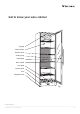
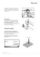
Get to know your wine cabinet Lighting Charcoal filter Wooden shelf Sealing strip Nameplate Door handle Kick plate Control panel Lock Adjustable feet fig.
Before use. Installation and start-up. On receipt, check to ensure that the appliance has not been damaged during transport. Transport damage should be reported to the local distributor before the wine cooler is put to use. Placement. Remove the packaging. Clean the inside of the cabinet using warm water with a mild detergent. Rinse with clean water and dry thoroughly (see cleaning instructions). Use a soft cloth.
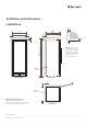
Dimension and Installation Guide Ventilation and dimensions. 130 Bottle Wine Cabinet V150SG2E-AL Vx 615 595 10 630 600 10 30 (see note) Tx Tx 1560 + Tx 1560 NOTE: If a vertical vent space (Vx) of 100mm is provided, then a minimum top ventilation gap (Tx) of 50mm is sufficient, but otherwise minimum Tx of 100mm is required. Spacer SIDE VIEW 10 FRONT VIEW 30 Spacer For complete installation instructions, please refer to the user manual for this product.
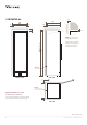
Dimension and Installation Guide 170 Bottle Wine Cabinet V190SG2E-AL 10 615 595 Vx 630 600 10 30 Tx Tx 1850 + Tx 1850 (see note) NOTE: If a vertical vent space (Vx) of 100mm is provided, then a minimum top ventilation gap (Tx) of 50mm is sufficient, but otherwise minimum Tx of 100mm is required. Spacer SIDE VIEW 10 FRONT VIEW 30 Spacer For complete installation instructions, please refer to the user manual for this product. 10 NOTE: Illustrations not to scale.
The distance pieces on the rear of the appliance ensure sufficient air circulation. Fit the two caps supplied with the appliance as shown in fig. 7. fig. 7 Setting up. It is important that the appliance be absolutely level. It can be levelled by screwing the adjustable feet at the front of the appliance up or down (figs 8-9). Use a spirit level to check that the appliance is absolutely level sideways. Technical data. fig.
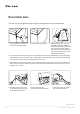
Reversible door. The door can be changed from right-hinged to left-hinged and vice versa as follows: GB 1. Lay the appliance on its back and loosen the upper hinge. 2. Remove the upper hinge. 3. Rotate the glass door 180° (On the smaller cabinets (1500mm) desmount the handle. The screws are on the inside of the sealing strip. Move the handle 400mm up and mount it again so it is in the same height as before.) 4.
8. When the lock pin has been loosened completely, pull it up together with the lock cylinder and refit on opposite side. 9. Click the covers into place on the plinth sides on the opposite side. 10. Fit the door onto the bottom pin, fit the top hinge and tighten securely. 11. After reversing the door, it is important to check that the sealing strip provides a tight seal all the way round. If it does not, carefully heat the strip all the way round using a hair dryer.
Operation and function. fig. 9 Electronic control The electronic control ensures that the temperatures set at the top and at the bottom of the appliance are maintained. This is achieved by means of an advanced control of the refrigeration system, the heating element, and the fan. The set temperature will be stored in the event of power failure.
Temperature setting at the bottom of the appliance Push SET2. Then the temperature at the bottom of the appliance can be adjusted up and down by means of the “up and down” buttons. The temperature can be adjusted from 5 to 22°C, however so that the temperature cannot be set at a higher temperature than the actual set point for the upper temperature sensor. Alarm devices There is a sub-alarm for the low-temperature sensor and an excess-alarm for the high-temperature sensor.
tom sections, the controls will maintain an even temperature throughout the cabinet. However, the temperature in the room will gradually affect the temperature in the cabinet through its door and sides, creating a slight temperature gradient from top to bottom. The controls will maintain the set temperature at the bottom of the cabinet, and any deviation from the setting will therefore occur at the top. The difference will vary from 0 to 3°C, depending on the ambient temperature.
Fault finding. Fault Possible cause Remedy The appliance is not working. The appliance is switched off. Press the on/off switch. Power failure; the fuse is blown; the appliance is not plugged in correctly. Check that power is connected. Reset the fuse. Water collects in the bottom of the cabinet. The defrost water pipe is blocked. Clean the defrost water channel and the drain hole on the rear wall of the cabinet. Vibration or bothersome noise. The appliance is not level.
Warranty, spare parts and service. Warranty disclaimer Faults and damage caused directly or indirectly by incorrect operation, misuse, insufficient maintenance, incorrect building, installation or mains connection. Fire, accident, lightening, voltage variation or other electrical interference, including defective fuses or faults in mains installations. Spare parts When ordering spare parts, please state the type, serial and product numbers of your appliance. This information is given on the rating plate.
Disposal Information for Users on Collection and Disposal of Old Equipment and used Batteries These symbols on the products, packaging, and/or accompanying documents mean that used electrical and electronic products and batteries should not be mixed with general household waste. For proper treatment, recovery and recycling of old products and used batteries, please take them to applicable collection points, in accordance with your national legislation and the Directives 2002/96/EC and 2006/66/EC.
Safety instructions (See also Warning page 2). 1. There is a name plate inside the cabinet. The name plate provides various technical information and a safety notice with a yellow flame triangle label, name and chemical symbol of the refrigerant. 2. The refrigerator contains flammable refrigerant (R600a: iso-butane). Requirements to ensure gas safety and safe use of refrigerators: ● The refrigeration system behind and inside the refrigerator contains refrigerant.
Warranty FOR SALES IN AUSTRALIA AND NEW ZEALAND APPLIANCE: ALL VINTEC/TRANSTHERM This document sets out the terms and conditions of the product warranties for Vintec/Transtherm Appliances. It is an important document. Please keep it with your proof of purchase documents in a safe place for future reference should there be a manufacturing defect in your Appliance. This warranty is in addition to other rights you may have under the Australian Consumer Law.
Service and support In the rare event that your Vintec cabinet does not perform to your satisfaction, contact our dedicated support team: 1800 771 776 concierge@vintecclub.com Vintec. We are part of the Electrolux Family. To add a touch of professional inspiration to your home, visit electrolux.com.au Stay in touch and share your user experience by following us: @vintecclub © 2018 Electrolux Home Products Pty Ltd. ABN 51 004 762 341 VMAN_V150-AL_V190-AL_ Jun18 vintec.