EN WINE CABINET FR ARMOIRE À VIN ES ARMARIO PARA VINOS USE AND CARE GUIDE GUIDE D’UTILISATION ET D’ENTRETIEN GUIA DE USO Y CUIDADO A18342801 September 2019
Finding Information Please Read and Save This Guide Make a Record for Quick Reference Thank you for choosing Vintec, the new premium brand in home appliances. This Use & Care Guide is part of our commitment to customer satisfaction and product quality throughout the service life of your new Wine Cabinet. We view your purchase as the beginning of a relationship. To ensure our ability to continue serving you, please use this page to record key product information.
Finding Information Questions? For toll-free telephone support in the U.S. and Canada:1-800-325-1371 For online support and Internet product information: www.vintec.com Table of Contents Finding Information.................................. 2 Important Safety Information.................... 4 Features.................................................. 7 Installation............................................... 8 Leveling................................................. 14 Controls and Settings............
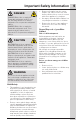
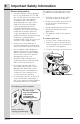
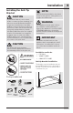
Important Safety Information Important Safety Instructions Safety Precautions Do not attempt to install or operate your unit until you have read the safety precautions in this manual. Safety items throughout this manual are labeled with a Danger, Warning or Caution based on the risk type. General Precautions WARNING RISK OF CHILD ENTRAPMENT. Before you throw away your old appliance, take off the doors and leave shelves in place so that children may not easily climb inside.
Important Safety Information DANGER DANGER Risk of fire or explosion. Flammable refrigerant used. Do not use mechanical devices to defrost refrigerator. Do not puncture refrigerant tubing. DANGER Risk of fire or explosion. Flammable refrigerant used. To be repaired only by trained service personnel. Do not puncture refrigerant tubing. CAUTION CAUTION Risk of fire or explosion. Flammable refrigerant used. Consult repair manual/owner’s guide before attempting to service this product.
Important Safety Information Electrical Information • • • • • • The Wine Cabinet must be plugged into its own dedicated 115 Volt, 60 Hz., 15 Amp, AC only electrical outlet. The power cord of the appliance is equipped with a three-prong grounding plug for your protection against electrical shock hazards. It must be plugged directly into a properly grounded three prong receptacle. The receptacle must be installed in accordance with local codes and ordinances. Consult a qualified electrician.
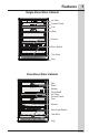
Features Single Zone Wine Cabinet Air Filter Control Panel Fan Shelf Sensor Door Switch Toe Grille Leg Dual Zone Wine Cabinet Fan Shelf Sensor Fixed Shelf Air Filter Control Panel Fan Sensor Door Light Switch Toe Grille Leg 7
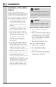
Installation Installation of Your Wine Cabinet Your Vintec Wine Cabinet has been designed for either free-standing or under counter installation. When under counter, your unit does not require additional air space for top, sides or rear. In either case, the front grille must NOT be obstructed. • This appliance is designed to be for free standing installation or under counter (fully recessed). (Refer to sticker located on the back of this appliance.
Installation Installing the Anti-Tip Bracket CAUTION If your Wine Cabinet is not located under a counter top (free standing), you must use an anti-tip bracket installed as per these instructions. If the Wine Cabinet is removed from its location for any reason, make sure that the bracket is properly engaged when you push the Wine Cabinet back into the original location.
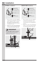
Installation DRYWALL installation: Bracket 1 B Hexagon Bolt 1/4" x 1.2" (1 pc) C Lock Washer (1 pc) D Flat Washer (1 pc) E Screw ST4x35 (2 pcs) 1. After you have chosen the installation location, place the bracket on the floor with (1) against the wall, use Screw (E) (2 pcs) to secure the bracket to the wall. Ensure at least one screw is secured into a stud. 2. Align lower corner of unit and bracket slot (A), secure with hexagon bolt (B), lock washer (C) and flat washer (D).
Installation 11 CONCRETE FLOOR installation: A Bracket 3 B Hexagon Bolt 1/4" x 1.2" (1 pc) C Lock Washer (1 pc) D Flat Washer (1 pc) F Expansion Screw 1/4" x 2.4" (1 pc) 1. After you have chosen the installation location, use either hole (3) to secure the bracket into the concrete floor. 2. Using a concrete bit, drill 8mm (3/8”) pilot hole 45mm (1.7”) deep. 3. Remove the nut, lock washer and washer from the expansion screw (F). 4.
Installation Installing the Wine Cabinet Your Vintec wine cabinet has been designed for either free-standing or under counter installation. When under counter, your wine cabinet does not require additional air space for top, sides or rear. In either case, the front grille must NOT be obstructed. NOTE To ease unit installation and removal, it is recommended that the cabinet rough opening dimensions be increased by at least ¼ inch over the dimensions given for your unit. 24" 610mm 24" 610mm 34.
Installation 13 Anti-Tip Installation for Under Counter Installation Instructions 1. NOTE Attach the anti-tip bracket with screws (2 pcs) in size M5 (12mm) onto the left hinge holes (if the door is being reversed, please fix the anti-tip bracket onto the right hinge holes) and then attach the other end of the anti-tip bracket onto the niche with the screws (2 pcs) in size ST4 (12mm).
Leveling Leveling the Unit Position the unit on a flat, level surface capable of supporting the entire weight of the unit when full. Leveling Legs Adjustable legs at the front and rear corners of the appliance should be set so the unit is firmly positioned on the floor and level from side to side and front to back. The overall height of your Vintec appliance may be adjusted between the minimum, 33 ¾” (85.7cm),by turning the leveling leg in and the maximum, 34 ¾” (88.
Controls and Settings 15 Single Zone Display Lights Settings Menu Power On/Off Simultaneously press and hold the Mode button and the increase button for 5 seconds to turn the unit power off or on. When the power is turned back on, the display will show the previous temperature settings. Press and hold for 3 seconds to enter/exit Lights Settings Menu. Both temperature displays blink and show a specific code. Any alert turns off temporarily. Press to increase/ decrease the “level”.
Controls and Settings °C/°F set Sabbath Mode Simultaneously press and hold the increase lower temperature set and light buttons for 5 seconds to toggle the temperature units °F and °C. Reset Filter alert Simultaneously press and hold the increase and decrease buttons for 5 seconds to activate/deactivate Sabbath mode. When activated, Lower and Upper temperature displays show “Sb” until deactivated.
Controls and Settings 17 Demo (Demonstration) mode The default setting for Control Sounds is On. Press once to toggle the display between ‘OF’ and ‘On’. The ‘OF’ or ‘On’ will display for 2 seconds then the display switches back to the previous temperature setting. This feature is programmed to show different displays of the unit; however, since unit will not activate the compressor, the unit will not cool. Demo mode is used for commercial purposes.
Controls and Settings Dual Zone Display NOTE Set temperature is shown while the temperature is being changed. Once complete, current temperature will show on display. Power On/Off Lights On/Off Simultaneously press and hold the Mode button and the increase button for 5 seconds to turn the unit power off or on. When the power is turned back on, the display will show the previous temperature settings. Upper Temperature Set Press to decrease/increase the set temperature.
Controls and Settings 19 Lights Behavior • Temperature display shows the light setting code: Lights Dim Level Bottom temperature display shows the light setting code. Press ∨ / ∧ to change the Dim Level. 1L: Lowest level / least bright (default) 2L:... 3L: Highest level / most bright • Opening or closing the door will not turn on or off any lights, digital readouts, solenoids, fans, valves, compressor, icons, tones, or alarms.
Controls and Settings Dual Cellaring Zone Press to toggle from Single/Dual Zone Mode to Cellaring Mode NOTE When activated, the display shows alternatively “dE” and “On” for 5 seconds. On Dual, Lower and Upper temperature display shows and blinks “dE” and “on” for 5 seconds. Any alert turns off temporarily. To keep communicating that the machine is in Demo mode, every 5 minutes, on Single, the display shows alternatively “dE” and “On” for 5 seconds.
Controls and Settings 21 High / Low temperature alert If a malfunction causes an either too high or too low temperature inside the cabinet, then the display on the control panel will indicate either “Hº” or “Lº” (High or Low temperature) and the alert icon will be illuminated. Door open alert When the door stays open for 5 minutes or more, the door open icon turns On and the lights start to dim and an alarm sounds. Any interaction on the Control panel will disable the alarms.
Door Reversal Accessory Bag Contents Metal washers (x2) Phillips Head™ Hinge pin bracket + + + Left side top hinge Left side bottom hinge Reversing the Door CAUTION Doors are heavy. Two people are recommended to remove or replace the door assembly from the cabinet. 1. To remove the top hinge pin, open the door and pull down the left top corner of the gasket. Use a flat screwdriver to remove the hinge pin retainer. Using screwdriver, push up on the top hinge pin and metal washer to remove. 2.
Door Reversal 23 3. Unscrew the bottom hinge pin bracket from the bottom of the door. Place door on a padded surface to prevent damage. 5. Unscrew the top hinge using a Phillips head screwdriver. CAUTION Door may slide if not held while performing this step since door is supported by a pin. + + + 4. Remove the plastic cover located on the opposite side of the door and place it where the hinge pin bracket was located. 6.
Door Reversal NOTE When replacing the hinge pin bracket, make sure there is proper alignment to maintain a good door seal. 8. Attach the hinge pin bracket on the bottom of the door. 9. Place the metal washer and door on the bottom hinge pin and align with the top hinge pin (with the right upper corner of the gasket pulled back) and install the top hinge pin and metal washer. Place the hinge pin retainer in place on the door, push gasket in place.
Storage Features 25 Shelf Removal NOTE CAUTION Never try to remove a loaded shelf, remove everything from the shelf before moving. Use both hands when moving the shelf. To remove single zone shelves: 1. Open the door completely and pull shelf out until it stops. 2. Using a screwdriver, remove the screws which connect the shelf to the rail on both sides of the shelf and pull the shelf out. 2 Single Zone Shelf Removal To remove dual zone shelves: 1.
Care and Cleaning Maintaining Your Wine Cabinet Periodic cleaning and proper maintenance will ensure efficiency, top performance, and long life. The maintenance intervals listed are based on normal conditions. You may want to shorten the intervals if you have pets or other special considerations. Exterior Cleaning • • • • • • • Your model may discolor when exposed to chlorine gas, pool chemicals, salt water, or cleaners with bleach.
Troubleshooting 27 Before You Call for Service If Service is Required If the unit appears to be malfunctioning, read through this manual first. If the problem persists, check the Troubleshooting Guide below. Locate the problem in the guide and refer to the cause and its remedy before calling for service. The problem may be something very simple that can be solved without a service call. Consulting or contracting a qualified service technician may be necessary.
Warranty 28 LimitedMajor Appliance Limited Warranty Your appliance is covered by a one year limited warranty. For one year from your original date of purchase, Electrolux will pay all costs for repairing or replacing any parts of this appliance that prove to be defective in materials or workmanship when such appliance is installed, used, and maintained in accordance with the provided instructions.