
Manual


MultiController II Installation
User Manual 3-9
Your installation may have from one to six heads installed. The power and data
cables are generally supplied by Vinten as part of the intial order. Additional or
replacement cables can also be ordered from Vinten.
Data Cables
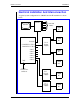
Two power supply configurations can be used with the MultiController II. PS-4
power supplies can be used to power and control up to four heads per supply. Or,
a PS-1 power supply can be used for each head. Or, you can use a combination
of both types of power supply. The diagram opposite shows both types of power
supply being used. The data cables you need to install will depend on your
power supply types..
The Control A connector on the MultiController II carries the data for cameras 1
through 4. The Control B connector carries the data for cameras 3 through 6.
Note that data for cameras 3 and 4 appears on both control connectors. There-
fore, if you are using two PS-4 power supplies, cameras 3 and 4 will be the #3
and #4 outputs on power supply A AND the #1 and #2 outputs on power supply
B. Make sure that you only connect a head to the head #3 and head #4 ports on
one power supply or the other - not both.
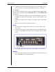
PS-4 Supply
Do not use the the CAM HEAD CTRL A or CAM HEAD CTRL B connectors
to control a camera that is already connected to an individual control connector
(CAM 1 through CAM 6).
1. Connect a data cable (25 pin D connectors) from the CAM HEAD CTRL A
connector on the MultiController II to the data input connector on the first
PS-4 power supply.
2. Connect power/data cables from the outputs on the power supply (7 pin
Lemo connector) to the respective pan/tilt heads (from 1 to 4 heads).
3. If you are using a second PS-4 for the remaining cameras, connect a data
cable (25 pin D connectors) from the CAM HEAD CTRL B connector on
the MultiController II to the data input connector on the second PS-4 power
supply.
Camera CTRL A
Camera CTRL B
Individual Camera Control