FCS-16 Fusion Control System Operators Guide V4035-4980 Robotic Camera Control Systems
Operators Guide Vinten Radamec FCS-16 Fusion Control System Publication Part No. V4035-4980 Issue 1 (April 2008) Original Instructions Copyright © Vitec Group plc 2008 All rights reserved throughout the world. No part of this document may be stored in a retrieval system. transmitted, copied or reproduced in any way including, but not limited to, photocopy, photograph, magnetic or other record without the prior agreement and permission in writing of Vitec Group plc.
Preface Thank you for buying the Vinten Radamec Fusion Control System. We want you to get the most from your new Fusion Control System (FCS), and therefore encourage you to read this operators guide to familiarize yourself with its many features. It also covers essential health and safety information and a section on maintenance that will ensure you keep your new product in perfect condition.
4
Safety - Read This First Understanding these instructions English The original instructions presented in this operators guide were written in English, and subsequently translated into other languages. If you are unable to understand these instructions, contact Vinten Radamec or your distributor to obtain a translation of the original instructions (EU Countries).
Latviešu Šajā operatora rokasgrāmatā iekļautie norādījumi sākotnēji tika sarakstīti angļu valodā un pēc tam pārtulkoti citās valodās. Ja nesaprotat šos norādījumus svešvalodā, sazinieties ar Vinten Radamec vai tirgotāju, lai saņemtu norādījumu tulkojumu (kādā no ES dalībvalstu valodām). Lietuvių Šiame operatoriaus vadove pristatomos pirminės instrukcijos parašytos anglų kalba ir vėliau išverstos į kitas kalbas.
Warning symbols in this operators guide Where there is a risk of personal injury or injury to others, comments appear highlighted by the word WARNING!—supported by the warning triangle symbol.
8
9
10
Contents Page Preface . . . . . . . . . . . . . . . . . . . . . . . . . . . . . . . . . . . . . . . . . . . . . . . . . . . . . . . . . . . . . . . . . . . . . . . . . . . . . . . 3 Safety - Read This First . . . . . . . . . . . . . . . . . . . . . . . . . . . . . . . . . . . . . . . . . . . . . . . . . . . . . . . . . . . . . . . . . 5 Regulatory information. . . . . . . . . . . . . . . . . . . . . . . . . . . . . . . . . . . . . . . . . . . . . . . . . . . . . . . . . . . . . . . . . . 7 Usage . . . . . .
Illustrations Page Fig 1 FCS-16 Fusion Control System . . . . . . . . . . . . . . . . . . . . . . . . . . . . . . . . . . . . . . . . . . . . . . . . . . . . . . 14 Fig 3 Main Screen . . . . . . . . . . . . . . . . . . . . . . . . . . . . . . . . . . . . . . . . . . . . . . . . . . . . . . . . . . . . . . . . . . . . . 16 Fig 4 Configuration Screen . . . . . . . . . . . . . . . . . . . . . . . . . . . . . . . . . . . . . . . . . . . . . . . . . . . . . . . . . . . . . .
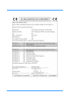
Technical data Weight FCS-16 Fusion Control System (including touch screen monitor and PC module) 7 kg (15.4 lb) PC module 0.5 kg (1.1 lb) Touch screen monitor (10.4”) 1.7 kg (3.3 lb) Height FCS-16 panel (including PC module and joysticks) 24.2 cm (9.5 in.) Touch screen monitor (10.4”) 19.2 cm (7.5 in.) Length FCS-16 panel (including PC module and joysticks) 48.3 cm (19 in.) Touch screen monitor (10.4”) 25 cm (9.84 in.) Width FCS-16 panel (including PC module and joysticks) 17.8 cm (7 in.
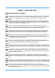
(17) (18) (1) (2) (16) (15) (3) (4) (14) (5) (13) (12) (11) (10) (9) (8) (7) (6) Fig 1 FCS-16 Fusion Control System (1) Touch screen (2) On air (Tally) indicators (3) Pan follow button (4) Joystick enable button (5) Bumper disable button (6) Target disable button (7) Panel disable button (8) Backup link button (9) Camera zoom/pan and tilt head control joystick (10) Camera preview buttons (11) Cut to shot button (12) Fade to shot button (13) Stop button (14) Fade t
(19) (20) (21) (22) Fig 2 Lightweight Control Panel, underside (19) PC module (20) USB ports (21) Power input socket (22) System fuse 15
(38) (23) (24) (37) (36) (35) (34) (33) (32) (31) (30) (29) (28) (27) (26) (25) Fig 3 Main Screen (23) Grid column header (24) Empty shot location (25) Options menu button (26) Page down button (27) Page up button (28) Sequence button (29) Focus shot button (30) Store shot button (31) Fade to shot button (32) Cut to shot button (33) Stop button (34) Edit shot button (35) Menu button (36) Camera select button (37) Grid row header (38) Show title 16
(54) (55) (39) (40) (41) (53) (42) (52) (43) (51) (44) (50) (49) (48) (47) (46) (45) Fig 4 Configuration Screen (39) Toggle zoom control direction (40) Toggle focus control direction (41) Toggle elevation control direction (42) Toggle always enable drive (43) Toggle always disable IR (44) Toggle always disable bumpers (45) Toggle require shot time (46) Toggle display shot time (47) Toggle require shot name (48) Return to main screen button (49) Toggle display shot name (50
Introduction The FCS-16 Fusion Control System enables an operator to remotely control cameras, pedestals, and pan and tilt heads. Used within a Fusion system configuration, the FCS-16 is compatible with current and many discontinued Radamec and AutoCam robotic products. Older system configurations will need updating to ensure compatibility—please contact Vinten Radamec or your local Vinten Radamec distributor for information (contact details are shown on the rear cover).
Operation User connections Users are only required to make connections to the panel USB ports. All other cable connections are made by trained engineers during the installation and commissioning of the system. The FCS-16 Fusion Control System has four USB 2.0 ports (18) located on the top of the panel, and another two (20) on the underside for devices located below the desk. The system has an integral PC module (19) which is compatible with PC USB 2.0 devices such as keyboards, mice and memory sticks.
Fig 5 Fusion pedestal targeting Fig 6 SP-2000 pedestal targeting RP2A pedestals continually reference a series of bar-code targets (line of sight), which are programmed and mapped during system commission and installation by trained personnel. Fusion and SP-2000 targets can easily be created by operators as required.
Create a datum To create a studio datum in the software, proceed as follows: 1. Select the CONFIGURATION MANAGER short-cut icon on the touch screen desktop. (Alternatively, select START > PROGRAMS > VITEC CAMERA DYNAMICS > FUSION ROBOTIC SYSTEM > CONFIGURATION MANAGER) 2. Select ADD from the ‘Targets’ section on the right-hand side. 3. Type a name for the datum, and enter the X and Y coordinates in millimetres. Fig 7 Fusion target origin Note: The master studio datum will have X and Y coordinates of 0,0.
2. Select the desired studio datum from the list on the right-hand side. 3. Select EDIT. 4. Re-type a name for the datum, and or re-enter the X and Y coordinates (in millimetres) as required. 5. Select OK 6. Select the ‘X’ in the top right-hand corner to close the application window. Delete a datum To delete a studio datum, proceed as follows: 1. Select the CONFIGURATION MANAGER short-cut icon on the touch screen desktop.
The Fusion FP-145 pedestal will drive itself at 45° across the target while optically scanning the floor to determine the datum position. When the pedestal stops moving the targeting function is complete. The SP-2000 pedestal will reposition and align itself to the floor target. When the pedestal stops moving the targeting function is complete. Note: To exit without performing either an ENABLE or TARGET command, select RETURN.
The grid display headers (23), (37) allow shots to be identified by their unique position in the grid display. These headers are particularly useful when the show extends over multiple pages. To turn these display headers on or off, proceed as follows: 1. Select MENU (35) > CONFIGURATION > DISPLAY HEADERS (55). Repeatedly selecting the display headers button (55) will toggle the function on and off. If the button (55) is coloured blue, then the function is active and headers will be displayed.
Delete a show To delete a stored show, proceed as follows: 1. Select MENU (35) > SHOW MANAGEMENT > DELETE SHOW. 2. Select the desired show from the scroll list. 3. Select ENTER. 4. Select OK to return to the main screen. Note: There is NOT an undo option following a show deletion. It is NOT possible to reinstate it. Select a camera The FCS-16 Fusion Control System can manage up to 16 cameras, with only one camera selected at any time.
• Brown camera select buttons (36) indicate that either or both the robotic head and pedestal are set in manual mode. Refer to the relevant head and pedestal operators guides for further detail. If a Fusion head is connected, it may be remotely switched to ‘Auto’ by ENABLING the camera unit. Please refer to Enable a camera unit on page 30 for further detail. • Yellow camera selection buttons (36) temporarily indicate that the control system is establishing communications with this camera unit.
Store a shot Once the camera unit is positioned as required, the shot position can be saved for later use in the show. Note: Shots cannot be stored if a show is not loaded or created. Please refer to ‘Use a show’ on page 24 for further detail. To store a shot in a show, proceed as follows: 1. Use the joystick controls to navigate the selected camera (10) to the required shot. Note: The selected camera video signal can be viewed on the preview monitor. 2. Select STORE (30). 3.
The camera will move to the shot position in the specified fade time, while a fade timer indicates progress in the touch screen stored shot location (24). When the camera is in position, the stored shot location turns from red to blue. Note: If the distance between the existing camera position and the desired shot position is small in relation to the specified fade time, the system moves to the shot in the fade time.
2. Select EDIT (34) > NAME. 3. Type in the desired shot name > ENTER. Note: The shot name can be a maximum of 16 characters long 4. To return to the main screen select > RETURN. Edit shot time To edit the shot time, proceed as follows: 1. Select the desired shot from the grid display (24). 2. Select EDIT (34) > TIME. 3. Type in the desired shot time (in seconds) > ENTER. 4. To return to the main screen select > RETURN. Delete shot To delete a shot, proceed as follows: 1.
Create a sequence of shots Please contact Vinten Radamec for further information regarding the sequence (28) function. Enable a camera unit Enabling a camera unit will re-establish communications with both the head and pedestal. This process also remotely switches a Fusion head from manual to automatic mode. Note: The camera unit must be re-targeted after enabling when switching from manual to automatic mode. Refer to ‘Target camera units’ on page 22 for further detail.
the pedestal control joystick (16) only allows robotic height movement. This feature prevents accidental pedestal travel while rotating the pedestal control joystick (16) to adjust camera height. Note: If ALWAYS ENABLE DRIVE (42) is selected in the system software (refer to ‘Always enable drive’ on page 32), the joystick control panel will have the JOYSTICK ENABLE function (4) activated by default.
Configure panel options Control panel options can be configured to suit the operator. To access these ‘panel options’, proceed as follows: 1. Select MENU (35) > SHOW MANAGEMENT > CONFIGURATION. 2. The panel option buttons DOUBLE BUTTON PUSH (51), ALWAYS OVERRIDE (50), ALWAYS ENABLE DRIVE (42), ALWAYS DISABLE IR (43) and ALWAYS DISABLE BUMBERS (44) are toggle buttons. Repeatedly selecting these buttons will toggle each function on and off. If a button is coloured blue then the function is active. 3.
Always disable bumpers Note: This function only affects Radamec RP2A pedestals. If ALWAYS DISABLE BUMPERS (44) is selected, the joystick control panel will have the BUMPER DISABLE function (5) activated by default (refer to Bumper disable on page 31). This will turn off the bumper protection facility on all connected Radamec RP2A pedestals (which arrests pedestal movement on collision with an obstacle). Configure shot options Required and displayed shot information can be configured to suit the user.
Servicing General The FCS-16 Fusion Control System is robustly made to high engineering standards and little attention is required to maintain serviceability save regular cleaning. Attention to the following points will ensure a long and useful service life with minimum need for repair. Cleaning WARNING! 1. Unplug this product from the wall outlet before cleaning. 2. This product has been designed for indoor use. Protect from water, moisture and dust.
To allow pedestals freedom of movement while targeting, the targets must not be too close to each other, the studio walls, or the set. There should be at least 100 cm (39”) of clear space around each pedestal when positioned at their targets. Initial target placement To temporarily place targets, proceed as follows: Clean the floor and place the targets in the selected location, securing them temporarily with adhesive tape.
The diagram in (Fig 9) shows the sign convention for determining positive and negative measurements from the absolute datum 0,0. Distances to the right of target #1 will be ‘+’ X, and distances to the left will be ‘-’ X. Similarly, positions forward of target #1 will be ‘+’ Y, and those to the rear of target #1 will be ‘-’ Y. Note: Although not essential, it is simpler if the datum target 0,0 is the left most target.
Re-calibrating the touch screen If the on-screen pointer no longer matches the operators finger position when using the touch screen, select the touch screen re-calibration desktop short-cut icon and run the application. For more detail please refer to the touch screen monitor user’s manual included with the system. Replacing the system fuse The system fuse (22) is located on the underside of the control panel.
Parts list The following lists include main assemblies, user-replaceable spare parts and optional accessories. For further information regarding repair or spare parts, please contact Vinten Radamec or your local distributor. For information on-line, visit our website at www.vintenradamec.com Item FCS-16 Fusion Control System Part No.