
Manual

19
Operation
User connections
Users are only required to make connections to the panel USB ports. All other cable connections are made by
trained engineers during the installation and commissioning of the system.
The FCS-16 Fusion Control System has four USB 2.0 ports (18) located on the top of the panel, and another
two (20) on the underside for devices located below the desk. The system has an integral PC module (19)
which is compatible with PC USB 2.0 devices such as keyboards, mice and memory sticks.
Plug the supplied keyboard and mouse into the top mounted USB ports (18).
If required, connect the power lead to the power input socket (21).
Switching on the panel
To switch on the Lightweight control panel, turn on the power switch (17). The integral PC module will boot-up
and begin loading the Windows operating system.
Create a user name and password
User accounts must be created before running the main Vinten Radamec Control (VRC) system software to
allow users to login. Two types of account can be created, a standard user account or a ‘super user’ account.
Super users can edit any saved shows, whereas standard users can only edit shows they’ve created.
To create a user account, proceed as follows:
1. Select the USER MANAGER short-cut icon on the touch screen desktop.
(Alternatively, select START > PROGRAMS > VITEC CAMERA DYNAMICS > FUSION ROBOTIC SYS-
TEM > USER MANAGER)
2. Select ADD USER.
3. Type in the user name and password.
4. If a super user account is required, tick the super user box.
5. Select OK.
Use a studio datum
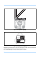
All robotic pedestal movements reference an absolute datum target; either permanently adhered to the studio
floor (Fig 5) (Fig 6) or mounted at the edge of the studio as a vertical bar-code (RP2A pedestals). Studio con-
figurations without pedestals do not need to reference a datum target position. In this instance, please refer
directly to Run the VRC program on page 22.
Note: On connection of power to the panel, all panel push buttons will sequentially illuminate
and then all extinguish after a period of approximately 3 seconds. This is a diagnostic
sequence verifying that all illuminating push buttons are operational.
Note: Ensure that the panel disable (7) or backup link (8) buttons are NOT illuminated before
attempting to use the panel controls. Refer to page 31 for more detail on these functions.