Robotic Camera Control Systems Vinten RADAMEC BROADCAST ROBOTICS FH-100 Robotic and Manual Pan & Tilt Head Operators Guide V3979-4980 Issue 3.
Fusion FH-100 Robotic and Manual Pan & Tilt Head Operators Guide Publication Part No. V3979-4980 Issue 3.
Copyright © Vitec Group plc 2009 All rights reserved throughout the world. No part of this document may be stored in a retrieval system. transmitted, copied or reproduced in any way including, but not limited to, photocopy, photograph, magnetic or other record without the prior agreement and permission in writing of Vitec Group plc. Trademarks Vinten Radamec® and Vinten® are registered trademarks of the Vitec Group plc.
Contents European Union Regulations . . . . . . . . . . . . . . . . . . . . . . . . . . . . . . . . . . . . . . . iii Safety Guidelines . . . . . . . . . . . . . . . . . . . . . . . . . . . . . . . . . . . . . . . . . . . . . . . . . . v Technical Data . . . . . . . . . . . . . . . . . . . . . . . . . . . . . . . . . . . . . . . . . . . . . . . . . . . vii Features and Controls . . . . . . . . . . . . . . . . . . . . . . . . . . . . . . . . . . . . . . . . . . . . viii Installation Instructions . . . . . .
List of Figures Figure 1 Standard Accessories . . . . . . . . . . . . . . . . . . . . . . . . . . . . . . . . . . . . .1 Figure 2 Vinten Heavy-duty Quickfix Adaptor. . . . . . . . . . . . . . . . . . . . . . . . . . .2 Figure 4 Fusion Pedestal to Head Power & EPL Connections . . . . . . . . . . . . . .6 Figure 5 Fusion Height Drive to Head Power & EPL Connections . . . . . . . . . . .7 Figure 6 Vinten Fusion Robot Control window . . . . . . . . . . . . . . . . . . . . . . . . .
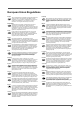
European Union Regulations Lietuvių English The original instructions presented in this operators guide were written in English, and subsequently translated into other languages. If you are unable to understand these instructions, contact Vinten Radamec or your distributor to obtain a translation of the original instructions (EU Countries). БЪЛГАРСКИ Оригиналните инструкции, представени в настоящото ръководство на производителя, бяха написани на английски език, а след това - преведени на други езици.
Disposing of old electronic equipment This symbol on the product or on its packaging indicates that this product must not be treated as household waste (applicable in the European Union and European countries with separate collection systems). It shall be handed over to the applicable collection point for the recycling of electrical and electronic equipment.
Safety Guidelines Servicing IMPORTANT Do not attempt to service this product. Opening and removing covers may expose you to dangerous voltages or other hazards. Refer all servicing to trained service personnel. Contact Camera Dynamics Ltd or your local distributor to arrange servicing of this product. Please read this manual carefully before attempting to operate the product. Retain this operators guide for future reference.
Safety when working with Robotic equipment Safe working environment In normal operation, remote controlled Heads and Pedestals can move suddenly and without warning. Since audible warnings are not suitable for use within the studio environment, it is recommended that only trained personnel be allowed to work in the active areas where remote controlled Heads and Pedestals are located. Personnel should be made aware of the potential hazards of working in a robotic environment.
Technical Data Physical Mounting Weight............................................................. 24.5 kg (54.0 lbs) Pedestal/tripod fixing ..................................... four-hole flat base Height to wedge adaptor mounting face ...............25.7 cm to 36.6 cm (10.1 in. to 14.4 in.) Quickfix base...................................heavy-duty Quickfix adaptor Height ............................................................. 51.9 cm (20.4 in.) Camera Lens Control Length..................
Features and Controls 8 1 7 2 7 6 5 3 4 Camera cradle clamp with 3 fixing screws . . . . . . . . . . . . . . . . . . . . . . . . . . . . . . . . . . . . . . . . . . . . . . . . . . . . 1 Camera cradle with camera mounting slots . . . . . . . . . . . . . . . . . . . . . . . . . . . . . . . . . . . . . . . . . . . . . . . . . . . 2 Teleprompter mounting holes . . . . . . . . . . . . . . . . . . . . . . . . . . . . . . . . . . . . . . . . . . . . . . . . . . . . . . . . . . . . . .
21 9 20 19 10 18 17 16 11 15 14 13 12 Tilt robotic/manual mode rotary switch . . . . . . . . . . . . . . . . . . . . . . . . . . . . . . . . . . . . . . . . . . . . . . . . . . . . . . . 9 Telescopic pan bar . . . . . . . . . . . . . . . . . . . . . . . . . . . . . . . . . . . . . . . . . . . . . . . . . . . . . . . . . . . . . . . . . . . . . 10 Pan robotic/manual mode rotary switch . . . . . . . . . . . . . . . . . . . . . . . . . . . . . . . . . . . . . . . . . . . . . . . . . . . . .
22 23 25 24 Four-hole mounting plate with Quickfix base . . . . . . . . . . . . . . . . . . . . . . . . . . . . . . . . . . . . . . . . . . . . . . . . . 22 Mounting plate fixing holes (4 off) . . . . . . . . . . . . . . . . . . . . . . . . . . . . . . . . . . . . . . . . . . . . . . . . . . . . . . . . . . 23 WEEE label . . . . . . . . . . . . . . . . . . . . . . . . . . . . . . . . . . . . . . . . . . . . . . . . . . . . . . . . . . . . . . . . . . . . . . . . . . .
Installation Instructions Out of the box Before unpacking the Head, always inspect the shipping container for evidence of damage and report any damage immediately. Always place the shipping container in the upright position as marked on the packaging. ! Warning! Heavy 24.5 kgs (54.0 lbs) Do not lift the Head by the camera cradle. 24.5 kg 54.0 lbs Remove the Head from the packaging, ensuring that all transport packing and retaining fixings are removed.
Mounting the head The Head has a standard Vinten four-hole mounting plate with a Quickfix base. The Head can be mounted onto a pedestal, typically the Fusion FP-188 pedestal, or onto a Vinten Heavy-duty tripod. CAUTION! Hold a fixing bolt in position through the mounting plate and ensure that the threaded end does not project more than 12 mm (15/32 in.) above the mounting plate face.
Mounting the camera and payload ! Warning! Do not exceed maximum total payload weight of 55 kg (121 lb) 55 kg 121 lbs Fitting the camera The Head is designed to allow the camera and payload to swing about its own centre of gravity (C of G), as opposed to balancing with the use of springs or cams. The camera and payload are mounted on to the camera cradle so the resulting centre of gravity aligns with the tilt-axis pivot point, providing true balance.
Fitting a vanity mirror A vanity monitor can be fixed to the front of the Head using the vanity monitor mounts. It is recommended that the vanity mirror is removed when operating the Head in robotic mode. Fitting a hand-control unit Vinten Radamec can supply a range of hand-control units designed to automate the switching of camera lens control (Canon or Fujinon) between robotic control and manual hand-controls.
Connecting to the Fusion Hand Control Interface The Fusion Hand Control Interface is mounted on to the underside of the camera cradle and is supplied with a single zoom/focus control cable that provides connection between the Head Zoom and Focus/Digital ports and the Zoom/focus control input port on the Hand Control Interface unit. The unit is also supplied with the appropriate cables for connection to the pan bar hand-controls and camera lens.
There are two EPL ports on the Pedestal control panel. One port is used to connect the Pedestal to the Control Panel via an EPL Node and the other port can be used to provide the EPL data communications to the Head.
Head EPL port Head Communication cable Head Power Output socket Figure 5 Fusion Height Drive to Head Power & EPL Connections Balancing the Head and payload Ensure that the Head and camera cradle are level before balancing. When the Head is correctly balanced, the robotic drives will need the minimum amount of even effort to move the Head. A correctly balanced Head and payload can be set to any tilt position and the Head will maintain that position hand’s off.
Setting fore and aft balance When positioning the payload it is important to be aware of the potential danger of an unbalanced payload falling away suddenly. Always be prepared for this by maintaining a firm hold on the payload until the balance has been set correctly. To set the fore and aft balance: 1. Hold and steady the camera cradle, and disengage the tilt lock (see Locking the camera cradle). Carefully release the camera cradle and observe how it moves and comes to rest. 2.
9. After balancing, exercise the Head through both axes to confirm that it operates smoothly. Note: Care should be taken when removing or repositioning any accessory equipment mounted to the camera cradle to ensure that the Head remains balanced—this includes repositioning the pan bar handles.
11. Click SET PAN,TILT, X/Y AND HEIGHT LIMITS to set the limits for the pan and tilt axes. The Set pan, tilt & height limits dialog box appears as shown in Figure 7.
g f Figure 7 Set pan, tilt & height limits dialog box (f) Pan maximum and minimum limits (g) Tilt maximum and minimum limits 12. Enter the angle of travel (in degrees) either side of the zero datum position for both pan and tilt axes.
From the Control Panel, carefully drive the Head to its limits in both pan and tilt axes using the joystick to determine if the limits have been correctly set. ! 12 Warning! Closely observe the camera movement while checking the software axis limits to avoid potential personal injury or damage to the equipment.
Operating instructions Powering up ! Warning! Ensure that all personnel and hazards are clear of Robotic equipment before switching the power ON. When the system is ready, ensure that all external cable connections are complete and the tilt lock is disengaged before switching the power ON. The Head should not move when power is switched ON, but zoom and focus will take up demanded positions on analogue lenses. The pan and tilt movements of the Head are controlled using the control panel joystick.
Operating the Head in Robotic mode ! Warning! Ensure that the Head is in view and clear from personnel and hazards before attempting to operate the equipment. Before operating the Head in robotic mode, it is recommended that any unnecessary equipment be removed from the payload, such as a vanity mirror. The Head must be re-balanced whenever equipment is removed or the pan bar handles adjusted. See Balancing the Head and payload.
Zero Pan Pan left Pan right Move joystick to the right to pan right. Move joystick to the left to pan left. Figure 10 Controlling pan movements using a joystick Move joystick backward to tilt the camera upward. Move joystick forward to tilt the camera downward.
Operating the Head in Manual mode ! Warning! The FH-100 Head can be used remotely from a Control Panel. Ensure that the Control Panel Operator does not attempt to select the camera whilst a Camera Operator is operating the Head manually. The Head can be operated manually by a camera operator using the bars to control the pan and tilt movements.
Adjusting the pan and tilt drag Both the pan and tilt mechanisms on the Head incorporate the patented Vinten lubricated friction (LF) system to ensure smooth movement of the camera about these axes and are fitted with dials to adjust the drag setting. The drag adjustment dials are mounted directly on each axis.
Maintenance ! Warning! To reduce the risk of electric shock, do not remove the cover. No user-serviceable parts inside. Refer to qualified service personnel. Routine checks During use, check the following: • Check the balance of the head. Re-balance as necessary. • Check the data communication with the control panel. Re-fit cables if necessary. • Check lens zoom and focus communication with the Head. Re-fit cables if necessary. No further routine maintenance is required.
Changing the fuse To replace a fuse: 1. Switch OFF power to the Head. 2. Carefully insert a small blunt screwdriver or similar tool into the side of the fuse compartment and lever out. 3. Lift out the fuse compartment (Figure 14). 4. Replace the failed fuse and then replace the fuse compartment, pushing firmly into place. 5. Switch ON power to the Head. Figure 14 Fuse compartment Adjusting the drag control dials The pan and tilt drag control dials may require adjustment after prolonged use.
Troubleshooting Fault Check Read Power supplied but the camera cradle is not moving. Check that the camera cradle tilt lock is disengaged. Locking the camera cradle Head not operating. Check that the power switch is ON. Powering up Ensure that the power and EPL cables are connected and secure. Power and EPL connections Check the power supply to the Head. Check that power is being supplied from the Pedestal or Height Drive or studio supply.
Parts List Part Number Main assemblies Fusion FH-100 robotic & manual pan and tilt Head . . . . . . . . . . . . . . . . . . . . . . . . . . . . . . . . . . . . V3979-0001 Standard accessories Fixing bolt . . . . . . . . . . . . . . . . . . . . . . . . . . . . . . . . . . . . . . . . . . . . . . . . . . . . . . . . . . . . . . . . . . . . . . L054-714 Washer - for fixing bolt . . . . . . . . . . . . . . . . . . . . . . . . . . . . . . . . . . . . . . . . . . . . . . . . . . . . . . . . . . . .
22
Index A abrasives 17 accessories, Optional 20 accessories, optional 1 accessories, standard 1, 20 B balance, check 19 balance, horizontal 8 balance, setting fore and aft 8 Balancing the head and payload 8 C cable restraint 7 cable, analogue focus 7 cable, analogue zoom 7 cable, ethernet 12 cable, Head Communication 5 cable, RS232 focus and zoom 7 cable, Studio Floor 5 cable, USB System Configuration 7 cables, camera lens 7 cables, dressed 5 Cables, Power and Ethernet 5 cables, power and ethernet, check 19
power connector, Height Drive 5 power inlet socket, Height drive 5 Power Output socket, Head 5 Power Output socket, Height drive 5 power supply unit, internal 5 power supply, studio 5 power, check supply 19 protective surfaces 17 Q Quickfix adaptor, mounting 2 Quickfix adaptor, releasing 2 Quickfix adaptor, Vinten heavy-duty 2 Quickfix base 2 R Regular cleaning 17 Robotic mode 14 robotic/manual rotary switches 14 Routine checks 17 S Spares 20 T teleprompter 3, 8 teleprompter, balance 8 tilt axis 12 tilt
CHINA The Vitec Group plc China Rm 706, Tower B Derun Building YongAn Dongli A No. 8 Jianwai Ave, Chaoyang District, Beijing, China 100022 Tel. +86 10 8528 8748 Fax. +86 10 8528 8749 FRANCE Camera Dynamics Sarl 171 Avenue des Grésillons 92635 GENNEVILLIERS Cedex France Tel. +33 820 821 336 Fax. +33 825 826 181 GERMANY Camera Dynamics GmbH Gebäude 16 Planiger Straße 34 55543 Bad Kreuznach Germany Tel. +49 671/483 43 30 Fax.