System Operators Guide PRO-10 Vinten Camera Control Solutions
protouch Pro-10 System Publication Part No. 3809-8 Issue 2 Copyright © Vinten Broadcast Limited 2005 All rights reserved throughout the world. No part of this document may be stored in a retrieval system, transmitted, copied or reproduced in any way including, but not limited to, photocopy, photograph, magnetic or other record without the prior agreement and permission in writing of Vinten Broadcast Limited. Vinten is a registered trademark of Vinten Broadcast Limited.
Safety - read this first Warning Symbols in this Operators Guide Where there is a risk of personal injury, injury to others, or damage to the pan and tilt head or associated equipment, comments appear, highlighted by the word WARNING! and supported by the warning triangle symbol. Technical data Pro-10 pan and tilt head Weight Head with bowl clamp Pan bar 2.5 kg (5.5lb) 0.25 kg (0.55 lb) Height to mounting face 13.8 cm (5.4 in.) Length 14.4 cm (5.7 in.) Width 15.8 cm (6.2 in.
Further information For full details on maintenance and spare parts, please refer to protouch Pro-10 System - Maintenance Manual and Illustrated Parts List (Publication Part No. 3809-9) This is obtainable from Vinten Broadcast Limited or your local Vinten distributor. For information on-line, visit our website at www.vinten.com.
Contents Page Safety - read this first . . . . . . . . . . . . . . . . . . . . . . . . . . . . . . . . . . . . . . . . . . . . . . . . . . . . . . . . 3 Technical data . . . . . . . . . . . . . . . . . . . . . . . . . . . . . . . . . . . . . . . . . . . . . . . . . . . . . . . . . . . . . . 3 Further information. . . . . . . . . . . . . . . . . . . . . . . . . . . . . . . . . . . . . . . . . . . . . . . . . . . . . . . . . . 4 Introduction Pro-10 pan and tilt head . . . . . . . . . . . . . . . . . . . . . .
(18) (1) (17) (2) (16) (3) (4) (5) (15) (6) (14) (7) (13) (8) (12) (11) (10) (9) Pro-10 Pan and Tilt Head 6
(1) 3/8 in. camera screw (2) Slide lock release (3) Pan bar (4) Tilt brake (5) Locating pin (6) 3/8 in. camera screw stowage (7) Camera slide plate clamp (8) Tilt drag control (9) Bowl clamp (10) Illuminated levelling bubble (11) Pan brake (12) Pan bar mounting (13) Levelling bubble illumination switch (14) Camera slide plate (15) Camera slide plate bung (16) Battery compartment (17) Pan drag control (18) 1/4 in.
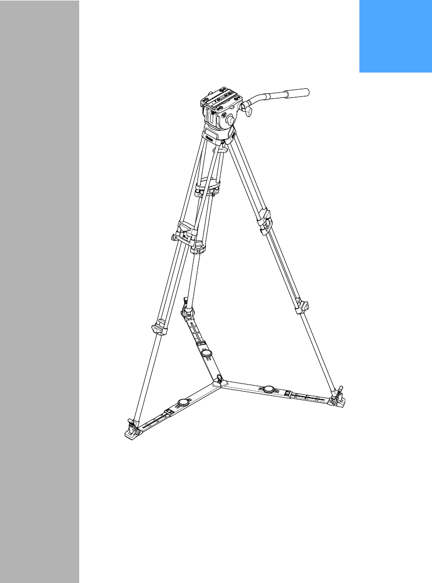
(26) (19) (25) (20) (24) (23) (22) (21) Pozi-Loc Tripod and Spreader 8
(19) Tripod bowl (20) Clamp knob (21) Floor spreader (22) Floor spreader adjuster (23) Foot securing strap (24) Leg tie strap (25) Attachment point for optional Spread-Loc mid-level spreader (26) Tie down hook 9
Introduction The protouch Pro-10 system from Vinten comprises a Pro-10 pan and tilt head, a Pozi-Loc twostage tripod, an adjustable floor spreader and a soft case. Pro-10 pan and tilt head The Pro-10 pan and tilt head is designed to support the latest professional digital video cameras, up to 10 kg (22 lb) in weight. It embodies fluid drag assemblies for pan and tilt motions with brakes on each axis to lock the head in any position.
Balance The balance spring in the Pro-10 pan and tilt head is set for an optimum payload of 7.5 kg (16.5 lb) at a centre of gravity (C of G) height of 12.5 cm (4.9 in.), but the head will support a payload of up to 10 kg (22 lb). The graph shows the relationship between C of G height and payload for optimum performance.
Each arm is of the spreader is adjustable for length (22) and the tripod feet are secured by rubber straps (23).
Operation Assembly If not already done, assemble the system as follows: Tripod and spreader Lift the tripod out of the case using the finger holes just below the top clamps. Release the leg tie strap (24) and spread the legs. Secure the spreader to the tripod feet with the rubber straps (23). NOTE: Once assembled, keep the spreader attached to the tripod Adjust the operating height by undoing the leg clamps (20) and pulling the tripod up to the desired height. Adjust the spreader (22) if necessary.
Push the slide plate and camera into the track in the platform, ensuring the slide lock release (2) snaps into position. Tighten the slide plate clamp (7). Pan and tilt brakes Brakes on each axis allow the head to be locked at any chosen position. The operating lever for the pan brake (11) is at the rear of the head. The tilt brake (4) is operated by a lever on the lefthand side of the head. To apply the brake, turn the lever fully clockwise. To release the brake, turn the lever counterclockwise.
Optional equipment Carrying strap A carrying strap (27) is available as an optional accessory and is installed as follows: On the lower moulding of the leg with the strap, drive in the 'knock-out' (24.1) using a suitable tool. If possible, remove the blank from inside the moulding to prevent subsequent rattle. (27.1) (27.2) (27.3) (27.4) (24.1) (27.5) (27.6) (19.1) (19.2) (27.
Push a blind captive nut (27.4) into the hole in the lower moulding. Using a suitable M5 screw, fully compress the blind captive nut. Remove the M5 screw. Install a washer (27.3) on the lower strap anchor (27.2) and screw into the captive nut (27.4). Ensure that the hole in the strap anchor is oriented so that the karabiner (27.1) can be attached On the underside of the tripod bowl (19), remove and discard the screw (27.5) securing the corresponding leg clamp (19.2). Do not remove the washer (19.1).
Dollies The Pro-10 system may be mounted on a variety of OB and studio dollies, which are listed under “Optional accessories” on page 16.
Servicing General Protouch products are robustly made to high engineering standards and little attention is required to maintain serviceability save regular cleaning. Attention to the following points will ensure a long and useful service life with minimum need for repair. Cleaning During indoor use, the only cleaning required should be a regular wipe over with a lint-free cloth. Dirt accumulated during storage may be removed using a semi-stiff brush.
Battery replacement The battery illuminates the level bubble (10) when the switch (13) is pressed. The level bubble remains lit for approximately 15 seconds. The battery should be replaced yearly or whenever the illumination is considered inadequate. To replace the battery: Tilt the head forwards to allow access to the battery cover (16) and apply the tilt brake (4). Push down on the top of the battery cover (16) and pull forward. Pull the battery (16.1) out of the battery compartment.
Adjustments Pan brake knob adjustment Because its movement is restricted, the pan brake knob (11) may require adjustment after prolonged use. To adjust the pan brake knob: Remove the securing screw (11.1) and pull the knob (11) off the shaft (11.2). Turn the shaft (11.2) clockwise until the pan brake is fully applied. Install the knob (11) on the shaft (11.2) approximately at right angles to the body of the head. Turn the knob fully counterclockwise and ensure the brake is released.
Camera slide plate knob adjustment To prevent interference with the payload, the camera slide plate knob (7) should be at or below the horizontal when applied. To adjust the camera slide plate knob: Remove the securing screw (7.1) and pull the knob (7) off the shaft (7.2). Turn the shaft (7.2) clockwise until the slide plate clamp is fully applied. Install the knob (7) on the shaft (7.2) approximately at or below the horizontal.
‘Pozi-Loc’ tripod leg clamp adjustment Bedding-in occurs with ‘Pozi-Loc’ leg clamps, which may necessitate resetting the clamp. Check the effectiveness of each leg clamp as follows: Extend all three tripod legs fully and apply the clamp(s). Position each leg in turn vertically on a set of weighing scales. Gradually apply body weight to the leg until either or both clamps begin to slip. Note the reading on the scales at which this occurs. A reading of less than 35 kg (77 lb) will necessitate adjustment.
Bottom clamp Adjust a bottom clamp as follows: Tighten the clamp (20) until an audible click is heard and the knob is in the locked position (POSITION 1). Using a suitable instrument, such as a flat-bladed screwdriver, carefully remove the knob cap (20.8). Remove the retaining screw (20.7) and washer (20.6), and pull off the clamp knob (20). Examine the shaft (20.3). If there is an identifying groove (20.4) on the shaft, proceed as follows.
Parts list The following lists include main assemblies, user-replaceable spare parts and optional accessories. For further information regarding repair or spare parts, please contact Vinten Broadcast Ltd or your local distributor. For information on-line, visit our website at www.vinten.com.
Dollies PD114 dolly U005-103 ENG (OB) dolly 3319-3B ENG (Studio) dolly 3319-3C ENG (OB) dolly - small 3319-3ST Tripod and pedestal adaptors 75 mm ball to 100 mm bowl adaptor U005-159 25