
User guide


Table Of Contents
- Contents
- 1. About This MegaCore Function Suite
- Release Information
- Device Family Support
- Features
- Design Example
- Performance and Resource Utilization
- 2D FIR Filter
- 2D Median Filter
- Alpha Blending Mixer
- Avalon-ST Video Monitor
- Chroma Resampler
- Clipper
- Clocked Video Input
- Clocked Video Output
- Color Plane Sequencer
- Color Space Converter
- Control Synchronizer
- Deinterlacer
- Deinterlacer II
- Frame Buffer
- Gamma Corrector
- Interlacer
- Scaler
- Scaler II
- Switch
- Test Pattern Generator
- Trace System
- 2. Getting Started with Altera IP Cores
- 3. Interfaces
- Interface Types
- Avalon-ST Video Protocol
- Avalon-MM Slave Interfaces
- Avalon-MM Master Interfaces
- Buffering of Non-Image Data Packets in Memory
- 4. 2D FIR Filter MegaCore Function
- 5. 2D Median Filter MegaCore Function
- 6. Alpha Blending MegaCore Function
- 7. Avalon-ST Video Monitor MegaCore Function
- 8. Chroma Resampler MegaCore Function
- 9. Clipper MegaCore Function
- 10. Clocked Video Input MegaCore Function
- 11. Clocked Video Output MegaCore Function
- 12. Color Plane Sequencer MegaCore Function
- 13. Color Space Converter MegaCore Function
- 14. Control Synchronizer MegaCore Function
- 15. Deinterlacer MegaCore Function
- Core Overview
- Functional Description
- Parameter Settings
- Signals
- Control Register Maps
- 16. Deinterlacer II MegaCore Function
- 17. Frame Reader MegaCore Function
- 18. Frame Buffer MegaCore Function
- 19. Gamma Corrector MegaCore Function
- 20. Interlacer MegaCore Function
- 21. Scaler MegaCore Function
- 22. Scaler II MegaCore Function
- 23. Switch MegaCore Function
- 24. Test Pattern Generator MegaCore Function
- 25. Trace System MegaCore Function
- A. Avalon-ST Video Verification IP Suite
- B. Choosing the Correct Deinterlacer
- Additional Information
Chapter 10: Clocked Video Input MegaCore Function 10–13
Control Register Maps
January 2013 Altera Corporation Video and Image Processing Suite
User Guide
2
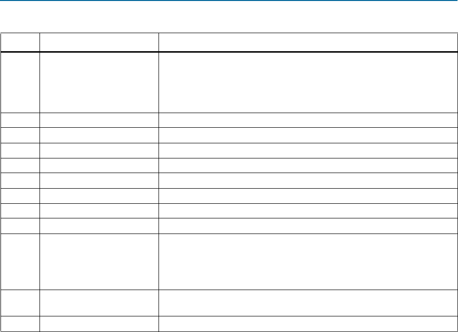
Interrupt
Bits 2 and 1 are the interrupt status bits:
■ When bit 1 is asserted, the status update interrupt has triggered.
■ When bit 2 is asserted, the stable video interrupt has triggered.
■ The interrupts stay asserted until a write of 1 is performed to these bits.
3
Used Words
The used words level of the input FIFO.
4
Active Sample Count
The detected sample count of the video streams excluding blanking.
5
F0 Active Line Count
The detected line count of the video streams F0 field excluding blanking.
6
F1 Active Line Count
The detected line count of the video streams F1 field excluding blanking.
7
Total Sample Count
The detected sample count of the video streams including blanking.
8
F0 Total Line Count
The detected line count of the video streams F0 field including blanking.
9
F1 Total Line Count
The detected line count of the video streams F1 field including blanking.
10
Standard
The contents of the
vid_std
signal.
11
SOF Sample
Start of frame sample register. The sample and sub-sample upon which the SOF
occurs (and the
sof
signal triggers):
■ Bits 0–1 are the subsample value.
■ Bits 2–15 are the sample value.
12
SOF Line
Start of frame line register. The line upon which the SOF occurs measured from
the rising edge of the F0 vertical sync.
13
Refclk Divider
Number of cycles of
vid_clk
(
refclk
) before
refclk_div
signal triggers.
Table 10–10. Clocked Video Input Control Register Map (Part 2 of 2)
Address Register Description