VK2-1080VFD Installation Guide
WARNING TO REDUCE THE RISK OF FIRE OR ELECTRIC SHOCK, DO NOT EXPOSE THIS PROCUCT TO RAIN OR MOISTURE. DO NOT INSERT ANY METALLIC OBJECT THROUGH THE VENTILATION GRILLS OR OTHER OPENNINGS ON THE EQUIPMENT. CAUTION EXPLANATION OF GRAPHICAL SYMBOLS The lightning flash with arrowhead symbol, within an equilateral triangle, is intended to alert the user to the presence of un-insulated "dangerous voltage" within the product’s enclosure that may be of sufficient magnitude to constitute a risk of electric shock.
CAUTION: CHANGES OR MODIFICATIONS NOT EXPRESSLY APPROVED BY THE PARTY RESPONSIBLE FOR COMPLIANCE COULD VOID THE USER'S AUTHORITY TO OPERATE THE EQUIPMENT. CE COMPLIANCE STATEMENT WARNING: This is a Class A product. In a domestic environment this product may cause radio interference in which case the user may be required to take adequate measures.
Contents 1. Description ................................................................................................. 6 2. Installation .................................................................................................. 8 2.1 Base installation .......................................................................................................8 2.2 Connection ...............................................................................................................9 2.
1. Description This manual applies to the VK2-1080VFD network camera. The VK2-1080VFD is fully featured for security surveillance and remote monitoring needs. It is based on the DSP compression chip, and makes it available on the network as real-time, full frame rate Motion JPEG and H.264 (or MPEG-4) video streams. The alarm input and alarm output can be used to connect various third party devices, such as, door sensors and alarm bells.
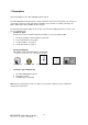
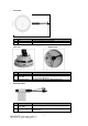
• Front View NO 1 2 • Cable Description 3-9mm varifocal IR corrected lens IP and Power connection cable • Side View NO 1 • Name Lens Connection Name Micro SD Slot 2 Status LED 3 Alarm IO Terminal Bottom View Description Micro SD slot for local recording Amber : On while System Booting Green : Normal Operation AI: Alarm Input, G: Ground, AO: Alarm Output Extension Cable NO Wire Colour Description 1 Red: DC12V White: GND Main Power, 2pin terminal, DC12V 330mA(4.
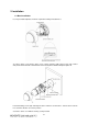
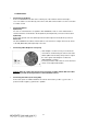
2. Installation 2.1 Base installation Use the provided template to mark the required mounting and cable holes. To remove dome cover, turn the dome cover counter clockwise until locators reach end of travel and pull off. Push the liner in the direction of the arrow (three ‘OPEN’ marks) and pull it off. Fasten Mounting screws (2X) and align the dome camera as shown above. Turn the dome camera in a clockwise direction to lock it in position. Secure the dome cover with the locking screw provided.
2.2 Connection • Connecting to the RJ-45 Connect a standard RJ-45 cable to the network port of the network camera. Generally a cross-over cable is used for directly connection to PC, while a direct cable is used for connection to a switch or hub. • Connecting Alarms AI(Alarm In) : You can use external devices to signal the VK2-1080VFD to react on events. Mechanical or electrical switches can be wired to the AI (Alarm In) and G (Ground) connectors in the bottom.
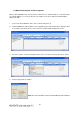
2.2 Network Connection and IP assignment When a VK2-1080VFD is first connected to the network it has a default IP address of 192.168.30.220 So, it will probably be necessary to allocate an IP address to the device with the “Smart Manager” utility on the CD. 1. Connect the VK2-1080VFD / device to the network and power up. 2.
3. Operation Before powering the camera, installation must be complete. The camera completes a configuration sequence taking approximately 40 seconds from powering up. Once completed the LED will be a constant Green. NOTES - If the DHCP is enabled but the camera is not connected to a DHCP server, the camera will be set to a default IP address of192.168.30.220 and will try to obtain an IP address from a DHCP server every two seconds.
4.0 Main Menu [Main Menu] The dialog box will be appears. - Type User ID and Password in the dialog box. The default User ID and Password are admin. NOTE For security purposes, be sure to change the password after you log on for the first time.
4.1 LIVE VIEW ------------------------------------------------------------------------------------------------------------------------- The Live View page provides you to select the properties of video source. You can view the live image from this page and also access the Setup menu and operate the main functions. [ Main Live View Page] Live Video Page Icons Hide Main Icons: Hides main icons in the live view page. Show Main Icons: Shows main icons in the live view page.
Help: Shows helpful information. Source: Specify the viewable video stream source to display in live view page. View Size: Specify the viewable video size to display in live view page. Stream Type: Specify the internet protocol to display in live view page. ROI View: Specify the specially selected area to transfer using different stream feature in the primary video image. ROI is an abbreviation for “Region of Interest”. Preset: Specify the Preset. This icon is inactivated if the PTZ settings are not set.
firmware version in your camera is displayed on the Basic Configuration or About. For the latest firmware of the camera, please contact with your product administrator. Detailed instructions on how to perform the upgrade process are provided with each new release. See also the Maintenance/ Upgrade for more information. 4.3 General Troubleshooting The following list covers some of the problems that may be encountered and suggests how to remedy them: 1. The camera cannot be accessed by some clients.
9. Poor image quality. → Increased lighting can often improve image quality. Check that there is sufficient lighting at the monitored location. Check all image and lighting settings. 10. Rolling dark bands or flickering in image. → Try adjusting the Exposure Control setting under AE and AWB part. 11. H.264 not displayed in the client. → Check that the correct network interface is selected in the Video & Image/Stream. 12. Multicast H.264 not displayed in the client.