200.4 models 500.
© 2002 Directed Electronics, Inc
CONGRATULATIONS Congratulations for choosing a Viper Audio power amplifier from Directed Electronics, the industry leader in high quality automotive security and audio equipment since 1990. With the introduction of Viper Audio power amplifiers, Directed Electronics continues to set new standards of performance, reliability, and affordability in the mobile electronics industry.
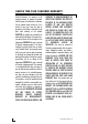
LIMITED TWO-YEAR CONSUMER WARRANTY Directed Electronics, Inc. promises to the original purchaser, to replace this product should it prove to be defective in workmanship or material under normal use, for a period of two years from the date of purchase by the dealer as indicated by the date code marking of the product PROVIDED the product was installed by an authorized Directed dealer.
FEATURES High-speed MOSFET switching power supply and complimentary bipolar outputs. Dual continuously variable 12 dB/octave two-way active crossovers. Four channel architecture supports up to six channel use. Dual switchable 8 dB bass EQ function. Thermal, DC offset, reverse polarity and short circuit protection. Summed stereo full-range RCA output jacks. Top-mounted controls located under illuminated Viper snake logo trim piece.
INSTALLATION GUIDELINES 1. Please read this owner’s manual carefully before installing this amplifier. 2. Disconnect the battery ground terminal prior to making any electrical connections. 3. Check for any hazards or obstructions such as gas tanks, fuel or brake lines, and wiring harnesses before mounting the amplifier. 4. Pick a mounting location that will provide adequate access and ventilation and protect the amplifier from heat, moisture, and dirt. 5.
speaker load, the more heat is generated. For low impedance speaker applications or restricted ventilation installations, an external cooling fan may be advisable. 9. Battery and ground connections to the vehicle should be made with crimped ring terminals of the appropriate size (surface area is what counts); soldering the terminals after crimping is also recommended. 10.
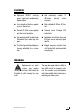
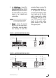
FRONT PANEL CONNECTIONS/STATUS LED 1. RCA Input Jacks - Accepts line level outputs from head units or signal processors at voltages between 150mV and 8 volts. 2. RCA Output Jacks - These pass through RCA jacks can be used to send a signal to a second amplifier. On four, five, and six channel amplifiers it is the summed stereo output of the one through four-channel inputs of the amplifier. 3.
4. (+) 12 Volt Power - Connect this terminal through a FUSE or CIRCUIT BREAKER to the positive terminal of the vehicle battery or the positive terminal of an isolated audio system battery. WARNING: Always protect this power wire by installing a fuse or circuit breaker of the appropriate size within 12 inches of the battery terminal connection. 5. Ground - Connect this terminal directly to the sheet metal chassis of the vehicle, using the shortest wire necessary to make this connection.
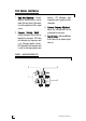
TOP PANEL CONTROLS 1. Input Gain Adjustment - Controls amplifier sensitivity and is used to match the input level of the amplifier to the output level of the signal source. 2. Crossover Selection Switch Controls the type of filter for the onboard active crossovers. FLAT does not attenuate any frequencies and is for full-range speaker systems. HPF attenuates low frequencies and is used for mid range speakers and tweeters. LPF attenuates high frequencies and is typically used for subwoofers. 3.
TOP PANEL FEATURES Control Panel Cover The amplifier’s gain and filter controls are mounted under the elliptical control panel cover. Magnets hold the cover snugly and allow easy access. To install the cover - Place the straight end of the control panel cover into the notched end of the amplifier’s top panel while elevating the curved end. Lower the curved end of the cover until the magnets make contact.
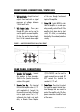
SPEAKER WIRING DIAGRAMS Stereo Operation (bottom view four channel shown) Bridged operation (bottom view two channel shown) NOTE: 12 For bridged two-channel operation as shown below, connect the right channel RCA cables to the Front inputs of the amplifier, and left channel RCA cables to the rear inputs of the amplifier. For summed subwoofer applications, connect the RCA cables per the input jack marking.
Simultaneous stereo/mono operation (bottom view) © 2002 Directed Electronics, Inc 13
CROSSOVER SETTINGS AND GAIN ADJUSTMENT Your Viper Audio power amplifier needs to be adjusted carefully to achieve maximum performance. These are some guidelines to follow when fine-tuning the amplifier. 14 For full-range and simultaneous stereo/mono bass applications, the crossover selection switch should be set to FLAT. If the amplifier is driving your subwoofers, set the switch to LPF, and for mid-bass/midrange output, set to HPF.
SPECIFICATIONS Viper model 200.4 500.4 RMS continuous power per channel, All channels driven into 4 ohms from 20 to 20,000 Hz, with less than 0.08% Total Harmonic Distortion @ 14.4 VDCC 35 watts 75 watts RMS continuous power per channel, All channels driven into 2 ohms from 20 to 20,000 Hz, with less than 0.1% Total Harmonic Distortion @ 14.4 VDC 50 watts 125 watts RMS continuous power, 2-channel operation, bridged into 4 ohms from 20 to 20,000 Hz, with less than 0.1% Total Harmonic Distortion @ 14.
The company behind this system is Directed Electronics, Inc. Since its inception, Directed has had one purpose, to provide customers with the finest vehicle security, car stereo products, rear seat entertainment, and accessories available. The recipient of more than 20 patents in the field of advanced electronic Directed Electronics, Inc. Vista, California 92083 www.directed.com technology, Directed is ISO 9001 registered.