® 550 ESP Installation Guide ® © 2001 Directed Electronics, Inc. Vista, CA N553 8-01 Rev. M 1.
Bitwriter™, Code Hopping™, DEI®, Doubleguard®, ESP™, FailSafe®, Ghost Switch™, Learn Routine™, Nite-Lite®, Nuisance Prevention Circuitry®, NPC®, Revenger®, Silent Mode™, Soft Chirp®, Stinger®, Valet®, Vehicle Recovery System®, VRS®, and Warn Away® are all Trademarks or Registered Trademarks of Directed Electronics, Inc. New Software Compatibility for 103T Keypad The Bitwriter® (p/n 998T) requires chip version 1.4 or newer to program this unit.
table of contents What is Included . . . . . . . . . . . . . . . . . . . . . 3 Warning! Safety First . . . . . . . . . . . . . . . . . . 4 Installation Points to Remember . . . . . . . . . . 5 Before Beginning the Installation . . . . . . . . 5 Finding the Tachometer Wire. . . . . . . . . . . . 5 Finding the Wait-to-Start Bulb Wire for Diesels. 6 After the Installation . . . . . . . . . . . . . . . . 6 Primary Harness (H1), 12-Pin Connector . . . . . 7 Secondary Harness (H2), 3-Pin Connector . . . .
warning! safety first The following safety warnings must be observed at all times: ■ Due to the complexity of this system, installation of this product must only be performed by an authorized DEI dealer. ■ When properly installed, this system can start the vehicle via a command signal from the remote control transmitter. Therefore, never operate the system in an area that does not have adequate ventilation.
installation points to remember before beginning the installation q IMPORTANT! This product is designed for fuel-injected, automatic transmission vehicles only. Installing it in a standard transmission vehicle is dangerous and is contrary to its intended use. ■ Please read this entire installation guide before beginning the installation. The installation of this remote start system requires interfacing with many of the vehicle’s systems.
finding the wait-to-start bulb wire for diesels In diesel vehicles it is necessary to interface with the wire that turns on the WAIT TO START light in the dashboard. This wire illuminates the bulb until the vehicle’s glow plugs are properly heated. When the light goes out the vehicle can be started. This wire is always available at the connector leading to the bulb in the dashboard. It can also be found at the Engine Control Module (ECM) in many vehicles. To test and determine the polarity of this wire: 1.
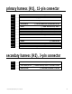
primary harness (H1), 12-pin connector H1/1 H1/2 H1/3 H1/4 H1/5 H1/6 H1/7 H1/8 ______ ______ ______ ______ ______ ______ ______ ______ ORANGE WHITE WHITE/BLUE BLACK/WHITE (-) 500 mA ARMED OUTPUT (+)/(-) SELECTABLE LIGHT FLASH OUTPUT (-) REMOTE START ACTIVATION INPUT (-) 200 mA DOMELIGHT SUPERVISION OUTPUT GREEN (-) DOOR TRIGGER INPUT, ZONE 3 BLUE (-) MULTIPLEXED INPUT, ZONE 4 VIOLET (+) DOOR TRIGGER INPUT, ZONE 3 BLACK (-) CHASSIS GROUND INPUT H1/9 ______ OPEN H1/10 ______ BROWN H1/11 ______
remote start primary harness, 5-pin connector 1 2 ______ ______ 3 ______ 4 ______ 5 ______ RED YELLOW PINK (+) CONSTANT POWER (+) IGNITION INPUT TO ALARM (-) 200 mA IGNITION RELAY TURN-ON ORANGE (-) 200 mA ACCESSORY RELAY TURN-ON PURPLE (-) 200 mA STARTER RELAY TURN-ON heavy gauge relay satellite key switch interface 1 2 3 4 5 6 ______ ______ ______ ______ ______ ______ RED (+) HIGH CURRENT 12V INPUT RED (+) HIGH CURRENT 12V INPUT PINK (+) OUTPUT TO PRIMARY IGNITION CIRCUIT ORANGE (+)
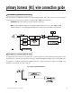
primary harness (H1) wire connection guide H1/1 ORANGE (-) ground-when-armed output This wire supplies a (-)500 mA ground as long as the system is armed. This output ceases as soon as the system is disarmed. The orange wire is pre-wired to control the DEI® 8618 Starter Kill Relay. IMPORTANT! Never interrupt any wire other than the starter wire. NOTE: If connecting the orange wire to control another module, such as a DEI® 529T or 530T window controller, a 1 amp diode (type 1N4004) will be required.
(-) Light Flash Output NOTE: For parking light circuits that draw 10 amps or more, the internal jumper must be switched to a (-) light flash output. (See the Internal Programming Jumper section of this guide.) P/N 8617 or a standard automotive SPDT relay must be used on the H1/2 light flash output harness wire. H1/3 WHITE/BLUE remote start (-) activation input A momentary input on this wire will start or stop the motor, just as transmitting Channel 3 from the remote transmitter does.
H1/5 GREEN (-) door trigger input, zone 3 Most vehicles use negative door trigger circuits. Connect the green wire to a wire which shows ground when any door is opened. In vehicles with factory delays on the domelight circuit, there is usually a wire that is unaffected by the delay circuitry. This wire will report Zone 3. H1/6 BLUE (-) multiplex input, zone 4 Inputs shorter than 0.8 seconds will trigger the Warn Away response, while inputs longer than 0.8 seconds will trigger the full alarm sequence.
H1/10 BROWN (+) siren output Connect this to the red wire of the siren. Connect the black wire of the siren to (-) chassis ground, preferably at the same point you connected the control module’s black ground wire. H1/11 RED (+)12V constant power input Before connecting this wire, remove the supplied fuse. Connect to the battery positive terminal or the constant 12V supply to the ignition switch. NOTE: Always use a fuse within 12 inches of the point you obtain (+)12V.
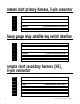
secondary harness (H2) wire connection guide H2/1 GRAY/BLACK (-) diesel wait-to-start bulb input Connect this wire to the wire in the vehicle that sends the signal to turn on the WAIT-TO-START bulb in the dashboard. In most diesels the wire is negative (ground turns on the bulb) and the GRAY/BLACK wire can be directly connected to the wire in the vehicle. If the vehicle uses a positive wire (12V to turn on the bulb) a relay must be used to change the polarity.
H2/2 LIGHT GREEN/BLACK (-) factory disarm output This wire sends a negative pulse every time the remote start is activated. This can be used to pulse the disarm wire of the vehicle's factory anti-theft device. Use a relay to send a (-) or (+) pulse to the disarm wire as shown in the diagrams below. This wire can also be used as a special accessory output. (See Feature Descriptions section of this guide.
relay satellite key switch interface wire connection guide The five heavy gauge wires coming from the relay satellite are used to energize high current circuits in the vehicle. It is crucial that these connections are well-made and capable of handling the current demands. For this reason, Scotch-Locks, T-taps and other such connectors are strongly discouraged.
remote start secondary harness (H3) wire connection guide H3/1 BLUE (-) status output This wire supplies a 200mA output as soon as the module begins the remote start process. It can be used with a relay to disconnect a sensor from the system as shown below. The H3/1 BLUE wire can also be used to rearm a factory anti-theft system when the remote start shuts down. (See the Feature Descriptions section of this guide.
H3/3 GRAY (-) hood pinswitch input, zone 1 This wire MUST be connected to hood pinswitch. This input will disable or shut down the remote start when the hood is opened. It will also trigger the security system if the hood is opened while the system is armed and report Zone 1. H3/4 BROWN (+) brake switch input, zone 1 This wire MUST be connected to the vehicle's brake light wire. This is the wire that shows (+) 12V when the brake pedal is depressed.
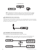
neutral safety switch interface Some vehicles do not have an electrical neutral safety switch. Instead, a mechanical neutral safety switch that physically interrupts the starter wire is used when the vehicle is in any drive gear. If the remote start is interfaced before this switch, it will provide protection from starting in gear. However, some vehicles combine the column shift mechanism and the mechanical neutral safety switch into one mechanical part.
If the starter engages and the vehicle is a General Motors product or Dodge Dakota pickup, refer to the following text and diagrams for an alternative shut-down method which will prevent the starter from engaging. If the vehicle is not a General Motors product or a Dodge Dakota pickup, please call DEI® Technical Support for an alternative shut-down method.
Pre-1996 Dodge Dakota pickups with 2.5 liter motors: 20 © 2000 Directed Electronics, Inc.
bypassing GM vehicle anti-theft systems (VATS) Vehicles with the GM VATS (Pass Key) systems have a resistor embedded in the ignition key. If the VATS decoder module does not measure the proper resistance when the vehicle is started, the starter and fuel pump may be disabled for up to ten minutes. An optional "VATS pack" of resistors is available (p/n 652T). One of the resistors in the pack will match the resistor in the key.
1995 and newer vehicle anti-theft systems (immobilizers) 1995 and newer vehicle anti-theft systems (immobilizers) require a bypass module. The bypass module allows for easy interfacing, while still maintaining the OEM system’s integrity.
ceiver will excite the transponder, which is located (but not visible) in the head of the ignition key. The key transponder will then send a unique code back to the transceiver for evaluation. If the code matches a valid code of the system, the vehicle will be allowed to start. Most of these transponder-based systems can be bypassed using p/n 555U. Some may require additional parts from the vehicle manufacturer. Consult you dealer for the applications.
shock sensor harness, 4-pin connector GREEN (-) multiplex input, zone 2 Inputs shorter than 0.8 seconds will trigger the Warn Away® response, while inputs longer than 0.8 seconds will trigger full alarm sequence and report Zone Two. If installing an optional DEI® dual stage sensor, connect to the green wire as shown below. The diagram below eliminates the need for diodes to isolate the sensors.
tach learning To learn the tach signal: 1. Start the vehicle with the key. 2. Within 5 seconds, press and HOLD the Valet®/Program switch. 3. The LED will light constant when the tach signal is learned. 4. Release the Valet®/Program switch.
type A: (+) 12V pulses from the switch to the factory relays The system can control Type A door locks directly, with no additional parts. The switch will have three wires on it, and one will test (+)12V constantly. The others will alternately pulse (+)12V when the switch is pressed to the lock or unlock position. If you cannot get to the switch, and you find a set of wires that pulse (+)12V alternately on lock and unlock, you must take care to ensure that it is not a Type C direct-wire system.
type B: (-) pulses from the switch to the factory relays This system is common in many Toyotas, Nissans, Hondas, and Saturns, as well as Fords with the keyless-entry system (some other Fords also use Type B). The switch will have three wires on it, and one wire will test ground all the time. One wire will pulse (-) when the switch locks the doors, and the other wire will pulse (-) when the switch unlocks the doors. This type of system is difficult to mistake for any other type.
Type C: Reversing Polarity, cont. type D: after-market actuators In order for this system to control one or more after-market actuators, a DEI® 451M or two relays (optional) are needed. Vehicles without factory power door locks require the installation of one actuator per door. This requires mounting the door lock actuator inside the door. Other vehicles may only require one actuator installed in the driver's door if all door locks are operated when the driver's lock is used.
type E: mercedes-benz and audi (1985 & newer) Type E door locks are controlled by an electrically activated vacuum pump. Some Mercedes and Audis use a Type D system. Test by locking doors from the passenger key cylinder. If all the doors lock, the vehicle's door lock system can be controlled with just two relays (optional). The control wire can be found in either kick panel and will show (+)12V when doors are unlocked and (-) ground when doors are locked. To interface see diagram below.
type G: positive (+) multiplex This system is most commonly found in Ford, Mazda, Chrysler and GM vehicles. The door lock switch or door key cylinder may contain either one or two resistors. When interfacing with this type of door lock system, two relays or a DEI 451M must be used. single-resistor type If one resistor is used in the door lock switch/key cylinder, the wire will pulse (+)12V in one direction and less than (+)12V when operated in the opposite direction.
type H: negative (-) multiplex The system is most commonly found in Ford, Mazda, Chrysler and GM vehicles. The door lock switch or door key cylinder may contain either one or two resistors. single-resistor type If one resistor is used in the door lock switch/key cylinder, the wire will pulse ground in one direction and resistance to ground when operated in the opposite direction.
internal programming jumpers tach threshold on/off In most cases, this jumper can be left in the OFF position. Some new vehicles use less than 12 volts in their ignition systems. The unit may have trouble learning the tach signal in these vehicles. Changing the jumper to the ON setting changes the trigger threshold of the digital tach circuit so it will work properly with these vehicles. These vehicles include many newer Dodge/Chrysler/Plymouths, such as the Neon Cirrus/Stratus/Breeze and LH-based cars.
™ transmitter/receiver learn routine The system comes with two transmitters that have been taught to the receiver. The receiver can store up to four different transmitter codes in memory. Use the following learn routine to add transmitters to the system or to change button assignments if desired. Using the optional DEI® Bitwriter™ or PC Interface, the learn routine may be locked. Make sure the learn routine is unlocked before programming features.
Channels Five, Six and Seven: Channels Five through Seven are used to assign the arm, disarm and panic functions to separate buttons on the remote control. Teaching a button to Channel Five erases all information about that remote from memory. Any auxiliary functions that are desired will have to be reprogrammed.
transmitter configurations The transmitters can be programmed with the standard or single button arm/disarm configurations by using the Auto Learn functions in the Transmitter/Receiver Learn Routine. standard configuration A remote that uses the standard configuration operates similarly to many factory keyless entry remotes. A standard configuration transmitter allows arming, disarming, and Panic Mode activation with separate buttons.
multi-level security arming Multi-Level Security Arming is a feature that allows the user to select which of the system's inputs or sensors will be active and which will be bypassed when the system is armed. (See Table of Zones section of this guide.) Multi-Level Security Arming can only be accessed from a standard configuration transmitter. Pressing the arm button of the standard configuration transmitter again within five seconds of arming the system will activate the Multi-Level Security feature.
system features learn routine The System Features Learn Routine dictates how the unit operates. It is possible to access and change any of the feature settings using the Valet/program switch. However, this process can be greatly simplified by using the optional Personal Computer Interface or Bitwriter (p/n 998T). Any of the settings can be changed and then assigned to one of up to four transmitters. This feature is called Owner Recognition.
NOTE: Some features have more than two possible settings. Pressing Channel One will select the one chirp setting, pressing Channel Two will toggle through the two-chirp and higher settings.) 6. Release. Release the Valet®/Program switch. Once a feature is programmed: ■ Other features can be programmed within the same menu. ■ Another menu can be selected. ■ The learn routine can be exited if programming is complete. To access another feature in the same menu: 1.
feature menus The default settings are indicated in bold type. Features that have additional settings that can be programmed using the Bitwriter are indicated with an asterisk (*).
menu #3 - remote start options FEATURE ONE-CHIRP SETTING (DEFAULT) TWO-CHIRP SETTING 3-1 Engine checking on Engine checking OFF 3-2 Engine checking TACH Engine checking VOLTAGE 3-3 Run time: 12 minutes* Run time: 24 or 60 minutes* 3-4 Parking lights flashing Parking lights constant 3-5 Crank time 0.6 seconds 0.8, 1.0, 1.2, 1.6, 1.8, 2.0, 4.
1-4 ACTIVE/PASSIVE LOCKING: If passive arming is selected in Feature 1-1, then the system can be programmed to either lock the doors when passive arming occurs, or only lock the doors when the system is armed via the transmitter. Active locking means the system will not lock the doors when it passively arms. Passive locking means that the system will lock the doors when it passively arms. NOTE: Remember, when passive arming is selected, the unit will chirp 20 seconds after the last door is closed.
menu #2 - advanced features 2-1 SIREN OUTPUT CONSTANT/PULSED: The system can be programmed to output pulses instead of a continuous output when the system is triggered. This is useful to honk the factory horn in applications where a siren is undesirable. Remember that the unit is only capable of supplying 1 amp of current. A relay will be required to interface with most factory horn systems.
2-7 IGNITION CONTROLLED DOME LIGHT SUPERVISION ON/OFF: If turned on, the system will turn on the dome light for 60 seconds when the ignition is turned off. The optional dome light supervision feature must be installed as described in the Wire Connection Guide. 2-8 DOUBLE PULSE UNLOCK ON/OFF: Some vehicles require two pulses on a single wire to unlock the doors. When the double pulse unlock feature is turned on, the BLUE H4/C wire will supply two negative pulses instead of a single pulse.
3-5 CRANK TIME 0.6/0.8/1.0/1.2/1.4/1.6/1.8/2.0/4.0 SECONDS: If the unit is programmed for no engine checking or voltage sense, the crank time must be set to the appropriate duration. The default setting is 0.6 second. If a different crank time is desired, select feature 3-5 and select either 0.6 second by using the onechirp setting or toggle through the higher settings by using the two-chirp settings. 3-6 VOLTAGE CHECK HI/LOW: This feature only functions when programmed for voltage sense.
valet mode To enter or exit valet mode with the valet/program switch: 1. Turn the ignition key on and then off. 2. At anytime during the next 10 seconds, press and release the Valet® switch. Now the Status LED will light constantly if you have entered Valet® Mode, and go out if you have exited Valet® Mode. To enter or exit valet mode with the transmitter: To enter or exit Valet® Mode with a transmitter: 1. Open any door. 2. Press on the transmitter. 3. Press . 4. Press again.
To enter or exit timer mode manually: 1. Make sure the remote start system is not operating the engine. 2. Turn the ignition on. Timer Mode will be exited and the parking lights will flash four times. table of zones When using the Diagnostic functions, use the Table of Zones to see which input has triggered the system. It is also helpful in deciding which input to use when connecting optional sensors and switches. ZONE NO.
LED FLASHES SHUTDOWN MODE One Timed out Two Over-rev shutdown Three Low or no RPM Four Transmitter shutdown (or optional push-button) Six (-) Shutdown (H3/3 GRAY) or (+) Shutdown (H3/4 BROWN) Seven (-) Neutral safety shutdown (H3/6 BLACK/WHITE) Eight Wait-to-start timed out long term event history The system stores the last two full triggers in memory. These are not erasable. Each time the unit sees a full trigger, the older of the two triggers in memory will be replaced by the new trigger.
safety check Before vehicle reassembly, the remote system must be checked to ensure safe and trouble-free operation. The following test procedure must be used to verify proper installation and operation of the system. The installation must be completed before testing, including connection to the brake switch and hood switch. 1. Test the BRAKE shutdown circuit: With the vehicle in Park (P), activate the remote start system. Once the engine is running, press the brake pedal.
troubleshooting alarm troubleshooting ■ Starter kill doesn't work: Is the correct wire being interrupted? If the car starts when the starter kill relay is completely disconnected, the wrong starter wire has been cut and interrupted. Is the yellow wire of the starter kill relay going to primary ignition? This wire must be powered in the run and start positions. ■ Shock sensor doesn't trigger the alarm: Has the NPC™ system been triggered? If so, you will hear 5 chirps when disarming.
remote start troubleshooting ■ The remote start will not activate. 1. Check the harnesses and their connections. Make sure that the harnesses are completely plugged into the remote start module. Make sure there are good connections to the vehicle wiring. 2. Check voltage and fuses. Use a meter to check for voltage between the red wire in the 5-pin ribbon harness and the black ground wire. If you have less than battery voltage, check the 3A and both 30A fuses on the relay satellite.
■ The climate control system does not work while the unit is operating the vehicle. Either the wrong accessory wire is being energized or more than one ignition or accessory wire must be energized in order to operate the climate control system. © 2000 Directed Electronics, Inc.
wiring quick reference guide 52 © 2000 Directed Electronics, Inc.