CD-ROM Box Enclosur e Enclosure Installation Guide For Models: VP-6020 VP-6022 VP-6023 VP-6024 VP-6028 VP-6029 VP-6048 VP-6049 We are your DataBridge TM http://www.vipower.
Table of Contents 1-1 Introduction ........................................................................... 1 1-1.1 CD-ROM Box Enclosure Features .............................. 1 1-1.2 ATA/ATAPI Device Compatibility ................................. 1 1-1.3 Unpacking Your CD-ROM Box .................................... 1 2-1 Installation ............................................................................ 2 2-1.1 Disassemble the CD-ROM Box ................................... 2 2-1.
1-1 Introduction Congratulations on your purchase of one of the following CD-ROM Box Enclosures. Each CD-ROM Box Enclosure is an external enclosure which is designed to enable portable, hot-swap, plug-and-play operation of same-interface type 5.25” devices installed in the box.
1-1.1 CD-ROM Box Enclosure Features • Enables portable use of 5.25” internal model removable media devices with computers equipped with the same interface • Supports hot-swap and plug-and-play features of the selected interface • Model VP-6020: enables cross-platform interface compatibility of 5.25” form factor IDE/ATA/ATA devices and ATAPI CD-ROM drives with computers using the same interface as the Docking Kit model (USB, Parallel, 1394/FireWire, SCSI, CARDBUS and PCMCIA). 1-1.
Retaining Screws (x4) Top Cover (Note alignment flanges) Vertical-Holder Stand (Optional) Connectors/Fan End-Panel Rubber Stands (x4) Bottom Cover (Note cut-out for flange) Drive Rails Retaining Screws (x4) CD-ROM Box Enclosure Components 2-1.2 Assemble CD-ROM Box with CD-ROM Drive 1. Attach the two connectors from the end-panel assembly to the appropriate connectors on the CD-ROM drive.
a. Attach the IDE 40-pin data cable from the end-panel to the 40-pin connector on the back of the CD-ROM drive. To ensure pin-1 to pin-1 connection, orient the cable so the colored stripe edge is closest to the power connector. b. Attach the 4-pin power cable from the end-panel to the 4-pin connector on the back of the CD-ROM drive. The connector is ‘D’ shaped to ensure proper connection. 2. Place the CD-ROM drive in the bottom enclosure cover.
6. Align the cover’s mounting holes with the mounting holes on the drive rails and secure with four screws (two on each side). 7. Replace the four rubber stands, one on each of the four corners. Orient each stand so the raised nub is on the bottom. These help heat dissipation and provide secure placement of the CD-ROM Box. Assembled CD-ROM Box Enclosure 8. A vertical-holder stand is also provided as a convenient, space-saving method for setup of the CD-ROM Box Enclosure on your desktop.
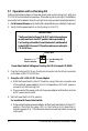
3.1 Operation with a Docking Kit Perform the following steps (in the order given) to set up a Docking Unit with your CD-ROM Box Enclosure for operation. (Also refer to your Docking Kit’s installation manual for further details. Some Docking Kits do not provide a Power Select switch.) 1. For Windows 98 users: verify that the Windows 98 driver is installed (if required.) 2. Verify that the power switch on the Docking Unit is OFF.
b. When using the Docking Kit’s interface for power, set switch to the RIGHT position. Note: it is recommended that you use the +5V /+12V power adapter whenever possible. 6. Connect the Docking Kit’s interface cable into the appropriate interface port on your computer; plug the other end into the connector port on the Docking Unit. 7. Viewing the screen, note that the plug-and-play feature will recognize the new device and assign it as a new drive. The device is now ready to use.