Digital Video Recorder The Networking model
Index Introduction to Digital Video Recorder------------------2 Front panel buttons-------------------------------------------3 Rear panel buttons ------------------------------------------4 DVR installation:video output connection--------------5 DVR installation:video input connection----------------5 DVR installation:sensor installation----------------------6 DVR installation:alarm installation------------------------7 Power up the unit --------------------------------------------8 On-screen dis
Introduction Introduction to Digital Video Recorder (DVR) The digital video recorder (DVR) is for recording/retrieving video streams from up to 4 channels at the same time. It adopts a digital image compression technology to compress the input channel video streams, and uses HDD to record the compressed video stream. The following operation guide explains how to operate/manage the DVR, and the following installation guide explains how to install DVR at your home or HDD into the DVR.
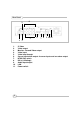
Front Panel 8 9 10 11 4 5 3 2 6 7 1 15 14 13 12 1. (Menu) button: press to display Operation menu option 2. z(Recording button): press to start recording. 3. (Stop recording/playback button):press stop recording/playback (the authorized password is requested upon stopping record; the default password is 111111) 4. (Fast forward button): press to play the recorded stream faster. 5. f (Playback button): press to start playback 6. (Pause button): press to pause the video playback 7.
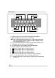
Rear Panel 2 1 3 1. 2. 3. 4. 5. 6. 7. 8. 9. 10. 11.
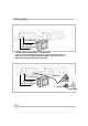
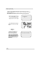
DVR Installation BNC connection Or through S-Video connection 1.Video input connection ( TV or monitor) Please connect TV(monitor) to the unit over the Video output connector. The unit provides 1 x S-Video input and 2 x BNC connector.The above Figure shows the video signal line connection.
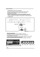
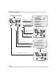
DVR Installation 2. Video output connection ( Camera) Please connect Camera to the unit over the Video input connector. The unit provides 4 x BNC connectors.The camera installation Procedures are as following: i. Connect the video signal line: connect the video signal line to the unit ii.Connect camera power line: Connect camera’s adaptor to camera, and plug in the adaptor. The complete connection with a camera will be shown as figure below Signal Line Sensor Power line AC/DC adaptor power outlet 3.
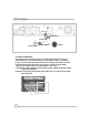
DVR Installation Signal Line Power line power outlet AC/DC adaptor Alarm 4. Alarm installation The unit provides 1 internal switch for sounding alarm when the sensor is Activated due to the unwanted entrance of anonymous visitor. The switch Is open at normal state, but, when the alarm is activated, the switch is closed So that the alarm gets the power. The circuitry is shown as above figure. There are two simple steps for the installation of the alarm i.
Power up the unit After the unit is properly installed ( please refer to Page 15-17 for more detailed on DVR installation.), the unit is ready to record and play. Then apply power and switch on.
On-Screen Display 1.
Operation guide MAIN MENU MAIN MENU CAMERA SELECT 1234 RECORD SELECT 1234 RECORD MODE 田 RECORD FRAMERATE 30 VIDEO QUALITY HI RECORD SCHEDULE SUB MENU HARD DRIVE SETUP SENSOR SETUP NETWORK SETUP Press to display menu option shown as right figure. Operation Buttons --- press to display menu option. ST--- press to change menu field or change the unit’s configuration values. --- press to select menu item or confirm the selection. ¾Please stop recording or playback before you enter into OSD menu.
Operation guide NOTICE Channel Display Control In each mode(回) mode, you can use the following buttons to display Full-screen format of each channel.
Operation guide There are two kinds of recording mode : 回(each mode; full screen mode)&田 (quad screen mode). when you set to 回mode, you can view the full-screen display of one specified channel. When you set to 田 mode, quadscreen will be displayed.
Operation guide VIDEO QUALITY MAIN MENU CAMERA SELECT 1234 RECORD SELECT 1234 RECORD MODE 田 RECORD FRAMERATE 30 ¾VIDEO QUALITY HI RECORD SCHEDULE SUB MENU HARD DRIVE SETUP NOTICE There are 3 different video quality settings for operation: Normal, Low, High Please use ¿À buttons of front panel to select mode and then enter to confirm the selection DIFFERENT VIDEO QUALITY SETTINGS ON HDD CAPACITY The higher the video quality is, the clearer images the unit plays.
Operation guide RECORD SCHEDULE MAIN MENU CAMERA SELECT 1234 RECORD SELECT 1234 RECORD MODE 田 RECORD FRAMERATE 30 VIDEO QUALITY HI ¾RECORD SCHEDULE SUB MENU HARD DRIVE SETUP SENSOR SETUP PROGRAMMED RECORD +TTTSSTTTTTTTTT+ 0 3 6 9 12 15 18 21 24 PRESS (¿À), THEN ( ) PRESS( ) TO EXIT Enter into this option to change a recording schedule during a day (24-hour period) . Numbers above indicate the time duration of 24 hours. (T) Letter indicates recording. (S) Letter indicates sensor recording.
Operation guide SUB MENU SUB MENU ¾PASSWORD CHANGE TIME SET DATE DISPLAY FORMAT Enter into this option to change password, time /date setting, date format. PRESS (¿À), THEN ( ) PRESS( ) TO EXIT PASSWORD CHANGE CURRENT PASSWORD: ------NEW PASSWORD:------PASSWORD CONFIRM:-------PRESS (¿À), THEN ( ) PRESS( ) TO EXIT NOTICE 15 PASSWORD CHANGE .
Operation guide TIME SET TIME 2004/03/21 03:23:21 PRESS (¿À), THEN ( ) PRESS( ) TO EXIT Enter into this option to change date and hour. DATE DISPLAY FORMAT DATE DISPLAY FORMAT PRESS (¿À), THEN ( ) PRESS( ) TO EXIT 16 The unit provides yyyy/mm/dd or dd/mm/yyyy variant which depends on the regional preference.
Operation guide HDD SETUP HARD DRIVE SETUP OVERWRITE ENABLED YES MASTER HDD SIZE 40000MB MASTER HDD USED 0MB 0% MASTER HDD FORMAT SLAVE HDD SIZE PRESS (¿À), THEN ( ) PRESS( ) TO EXIT OVERWRITE ENABLED: If you choose “YES”, the unit will continue recording and overwrite the recorded data when HDD’s space is full If you choose “NO”, the unit will stop recording while HDD’s space is full MASTER HDD SIZE: It indicates the capacity of the primary HDD installed in the unit MASTER HDD USED: It indicates how perc
Operation guide SENSOR SETUP SENSOR SETUP SENSOR RECORD TIME 15 ALARM OUT TIME 20 CHANNEL-1 TYPE:MOTION + N-C CHANNEL-2 TYPE:MOTION + N-O CHANNEL-3 TYPE:NORMAL CLOSE CHANNEL-4 TYPE:NOT INSTALLED PRESS (¿À), PRESS( SENSOR RECORD TIME: Recording duration once sensor Being triggered. ALARM OUT TIME: It controls how long ( in second) the alarm sounds after being triggered. THEN ( ) ) TO EXIT SENSOR TRIGGER MODES: The unit provides 5 different modes for variant uses: 1.Not installed. 2. Normal open. 3.
Operation guide How to operate Motion detection recording SENSOR SETUP SENSOR RECORD TIME 15 ALARM OUT TIME 20 CHANNEL-1 TYPE:MOTION + N-C CHANNEL-2 TYPE:MOTION + N-O CHANNEL-3 TYPE:NORMAL CLOSE CHANNEL-4 TYPE:NOT INSTALLED PRESS (¿À), PRESS( THEN ( ) ) TO EXIT PROGRAMMED RECORD +TTTSSTTTTTTTTT+ 0 3 6 9 12 15 18 21 24 PRESS (¿À), THEN ( ) PRESS( ) TO EXIT 19 Follow the steps as below to activate motion-detection recording. 1.Please go to “SENSOR SETUP” menu as the left figure shown. 2.
Operation guide NETWORK SETUP NETWORK SETUP ACCEPT IP YES MAC ADDRESS 03:01:01:01:25:46 IP ADDRESS 192.168.000.090 SUBNET MASK 255,255,255,000 GATEWAY 192.168.000.001 PRESS (¿À), PRESS( The first option “enabled network client”, please make sure is set to YES 2) MAC setting will not need to be altered. 3) *IP address (a static IP address ) will need to be set to the DVR IP address you planning to allocate to, while you connect to Internet.
Operation guide PLAYBACK Please use the front panel buttons to operate various playback functions. SEARCH TIME HDD: MASTER 04/03/24 13:24:21-04/03/24 13:44:54 >01 TIME 04/03/24 13:24:21 >02 TIME 04/03/24 13:30:55 >03 TIME 04/03/24 13:40:54 (¿À) MOVE,( ) CHANGE,(f)PLAY NOTICE Press “f” button, then the playback time /events selection menu as the left figure appears on the screen. Or you can simply press “f” twice to directly start playing.
Appendix I. Regulatory FCC Certification This equipment has been tested and found to comply with the limits for a class A digital device, pursuant to Part 15 of the FCC rules. These limits are designed to provide reasonable protection against harmful interference when the equipment is operated in a commercial environment.
Appendix II. Networking This Unit with the dedicated remote PC client software allows you from a remote location to view live and recorded video over Internet. Also, you can capture,convert the video from the unit into AVI file or JPEG file, or play the stored video later on. Please follow the instructions below to use PC client.
Appendix II. Networking 1. How to connect to the DVR click on “Connect” option on Main window Click on “Connect “ to enter into “DVR Client connection manager” As the following dialog window: 1. 2. DVR IP: The DVR iP address is the IP address of the remote DVR. Password : The password is same password used for formatting the DVR’s Hard Drive.
Appendix II. Networking 2. Connection Status: When successfully connected, you would see” Connected” sign. This window also displays DVR IP address and shows changes of connection speed.
Appendix II. Networking 3. DVR control The panel shown as the following figure operates exactly as the remote DVR operational button allow you to control remote DVR to live view, record and playback as well.
Appendix II. Networking 4. Capture & Playback on you PC 4-1 Capture video data When you click “REC” button, it will start to record the incoming video on your PC hard disk. The DVR client creates “ steam_files”folder where the execution file is located. When the client is recording, the Capture & Play status indicator would show the current status, REC. 4-2 Playback After recording is finished, click” Play” button to play the recorded video stream.
Appendix II. Networking 5. DVR management This option enable you to just remote DVR’s operation setting : Video Quality, Record Frame rate, Alarm On Duration, Alarm record Duration, Input Channels, Record Channels, DVR system time setting and Record Schedule. All of settings operate as you do with DVR itself. Notice: For the record mode change can be made only on DVR, so the display shows the current DVR record mode on connection.
Appendix II. Networking 6. AVI file Click on this button to convert the real-time video data or the recorded data into AVI file 6. Click on “ AVI save as” button to convert the desirable data into AVI file, then you will see the following dialog box for saving the AVI file. After specifying the file name and confirmation, please click on “ Backup to AVI” to start the conversion.
Removable Docking Modules for IDE or USB Devices Super Rack Models: VP-10LSFU-100/133 VP-10KPFU-100/133 VP-410LS2FU-100/133 VP-410KP2FU-100/133 VP-15-100/133 Super Rack 1-1
1-1 Introduction ........................................................................ 1-3 Super Rack Features .................................................... 1-4 System Requirements ................................................... 1-4 Unpacking Your Super Rack ......................................... 1-5 IDE Basics .................................................................... 1-5 USB Basics ...................................................................
1-1 Introduction Congratulations on your purchase of an ATA 33/66/100/133 Super Rack Removable Docking Module. The Super Rack is a convenient, versatile solution for portable, interchangeable usage of both IDE and USB devices with your USB-equipped PC or Mac computer. The Super Rack is form-fitted for a standard 5.25" half-height bay. When installed in your computer, it provides the ATA 33/66/100/133 interface for hot-swapping any IDE in-tray box (with IDE devices such as 3.5”/2.
Model Number Code Descriptions for Ordering Information: VP-1 0 L S F S 1 1 2 3 4 5 6 7 2 3 4 5 6 7 ViPowER .................. Interface Type .......... Body ........................ Lock Type ................ Power Switch ........... Cooling Fan ............. USB Solution ...........
Unpacking Your Super Rack Before installing the Super Rack, verify that the following items are included in the carton. If any parts are damaged or missing, please contact your local dealer or sales representative immediately. 1. 2. 3. 4. 5.
1-2 Hardware Installation The Super Rack Docking Module is designed to install in any PC or Mac computer with an available 5.25-inch half-height drive bay. General instructions for installing the Super Rack are given since the design of computer cases varies. Refer to your computer’s manual whenever in doubt.
Power Connector Data Interface Cable Bottom Mounting Holes Side Mounting Holes Handle Removable Front Panel for Removable Media Drives Super Rack In-Tray Box VP-15 (with cover removed) Installing the Super Rack Out-Frame 1. Turn OFF the power to your computer and any other connected peripheral devices. Follow the precautions for static electricity discharge: • Discharge any static electricity build up in your body by touching a grounded metal surface such as the computer case, if plugged in.
7. Position the out-frame so its mounting holes align with the drive bay’s mounting holes. Secure with the supplied mounting screws (two on each side.) 8. Attach an existing IDE 40-pin data cable from the system motherboard (or IDE controller card) to the 40-pin connector on the back of the out-frame. Most connectors are keyed for proper insertion. If there is no key, orient the cable so the pin-1 colored stripe edge is closest to the power connector. 9.
Perform the following steps to enable the USB function of the Super Rack. 1. With the computer cover removed, ensure the power is OFF, and all power cords and cables from the back of the computer are unplugged. 2. Select an unused I/O expansion slot at the back of your computer and remove its slot cover. Save its screw for securing the USB slot bracket. 3. Install the USB slot bracket and secure with the previously removed screw. 4.
Mounting a Drive in the In-Tray Box (VP-15) Proceed with the following steps to install a 3.5-inch drive device in the in-tray box. (Note: a special adapter kit is required in order to install a 2.5-inch drive.) 1. Remove the in-tray box cover by sliding it towards the back of the unit. Slide Cover Off Remove the In-Tray Box Cover 2.
4. Connect the cables from the in-tray box to the appropriate pin connectors of the drive. The in-tray box’s 40-pin IDE cable supports 3.5-inch drives. Attach the power and IDE cables from the in-tray box to the drive. The power connector is ‘D’ shaped to correctly orient the connector. The colored stripe on the IDE cable should be closest to the power connector. To install a 2.5-inch drive, you must purchase a ‘44-pin to 40-pin’ connector adapter from your local computer dealer. 5.
1-3 Using the Super Rack Latch-Lock models VP-10LSFU/VP-410LS2FU, and Key/Power Lock models VP-10KPFU/VP-410LS2FU support hot-swapping. The power to your computer can be ON when the drive is inserted or removed. Use the Latch-Lock switch or Key/ Power Lock keyswitch to turn power to the drive ON after inserting it, and OFF before removing it. To insert the in-tray box: 1. Insert the in-tray box (with drive installed) into the installed Super Rack out-frame and push firmly until the drive is seated. 2.
1-4 Using the Super Rack with USB In-Trays Example USB 1.1 4-port Hub ( VP-15H ) (Comes with USB I/O Expansion Slot Bracket) Latch-Lock models VP-10LSFU/VP-410LS2FU, and Key/Power Lock models VP-10KPFU/VP-410LS2FU support plug-n-play, hot-swapping of USB in-tray devices such as USB hub, fax/modem, memory card readers and TV/FM/capture models. The power to your computer can be ON when the in-tray is inserted or removed.
1-14 Super Rack