
Datasheet

Molded Guide
www.vishay.com
Vishay Sprague
Revision: 02-Aug-18
5
Document Number: 40074
For technical questions, contact: tantalum@vishay.com
THIS DOCUMENT IS SUBJECT TO CHANGE WITHOUT NOTICE. THE PRODUCTS DESCRIBED HEREIN AND THIS DOCUMENT
ARE SUBJECT TO SPECIFIC DISCLAIMERS, SET FORTH AT www.vishay.com/doc?91000
Notes
• Metric dimensions will govern. Dimensions in inches are rounded and for reference only.
(1)
A
0
, B
0
, K
0
, are determined by the maximum dimensions to the ends of the terminals extending from the component body and / or the body
dimensions of the component. The clearance between the ends of the terminals or body of the component to the sides and depth of the
cavity (A
0
, B
0
, K
0
) must be within 0.002" (0.05 mm) minimum and 0.020" (0.50 mm) maximum. The clearance allowed must also prevent
rotation of the component within the cavity of not more than 20°.
(2)
Tape with components shall pass around radius “R” without damage. The minimum trailer length may require additional length to provide
“R” minimum for 12 mm embossed tape for reels with hub diameters approaching N minimum.
(3)
This dimension is the flat area from the edge of the sprocket hole to either outward deformation of the carrier tape between the embossed
cavities or to the edge of the cavity whichever is less.
(4)
This dimension is the flat area from the edge of the carrier tape opposite the sprocket holes to either the outward deformation of the carrier
tape between the embossed cavity or to the edge of the cavity whichever is less.
(5)
The embossed hole location shall be measured from the sprocket hole controlling the location of the embossement. Dimensions of
embossement location shall be applied independent of each other.
(6)
B
1
dimension is a reference dimension tape feeder clearance only.
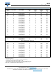
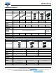
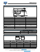
PLASTIC TAPE AND REEL PACKAGING in inches [millimeters]
Tape and Reel Specifications: all case sizes are available
on plastic embossed tape per EIA-481. Standard reel
diameter is 7" [178 mm], 13" [330 mm] reels are available and
recommended as the most cost effective packaging method.
The most efficient packaging quantities are full reel
increments on a given reel diameter. The quantities shown
allow for the sealed empty pockets required to be in
conformance with EIA-481. Reel size and packaging
orientation must be specified in the Vishay Sprague part
number.
CASE
CODE
TAPE
SIZE
B
1
(MAX.)
D
1
(MIN.)
F
K
0
(MAX.)
P
1
W
MOLDED CHIP CAPACITORS; ALL TYPES
A
8 mm
0.165
[4.2]
0.039
[1.0]
0.138 ± 0.002
[3.5 ± 0.05]
0.094
[2.4]
0.157 ± 0.004
[4.0 ± 1.0]
0.315 ± 0.012
[8.0 ± 0.30]
B
C
12 mm
0.32
[8.2]
0.059
[1.5]
0.217 ± 0.00
[5.5 ± 0.05]
0.177
[4.5]
0.315 ± 0.004
[8.0 ± 1.0]
0.472 ± 0.012
[12.0 ± 0.30]
D
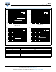
E
V
W
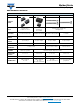
0.004 [0.1]
MAX.
K
0
Tape thickness
B
1
MAX.
(Note 6)
0.014
[0.35]
MAX.
± 0.008 [0.200]
Embossment
0.069 ± 0.004
[1.75 ± 0.10]
D
1
MIN. for components
0.079 x 0.047 [2.0 x 1.2] and larger .
(Note 5)
Maximum
cavity size
(Note 1)
USER DIRECTION OF FEED
Center lines
of cavity
A
0
P
1
F
W
0.030 [0.75]
MIN. (Note 4)
0.030 [0.75]
MIN. (Note 3)
0.079 ± 0.002
[2.0 ± 0.05]
0.157 ± 0.004
[4.0 ± 0.10]
0.059 + 0.004 - 0.0
[1.5 + 0.10 - 0.0]
B
0
Maxim um
component
rotation
(Side or front sectional view)
20°
For tape feeder
reference only
including draft.
Concentric around B
0
(Note 5)
Deformation
between
embossments
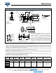
Top
cover
tape
Top
cover
tape
10 pitches cumulative
tolerance on tape
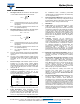
Direction of Feed
Anode (+)
Cathode (-)
20° maximum
component rotation
Typical
component
cavity
center line
Typical
component
center line
A
0
B
0
(Top view)
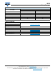
0.9843 [250.0]
Tape
3.937 [100.0]
0.039 [1.0]
MAX.
0.039 [1.0]
MAX.
Camber
(top view)
Allowable camber to be 0.039/3.937 [1/100]
non-cumulative over 9.843 [250.0]