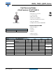
40HFL, 70HFL, 85HFL Series Vishay High Power Products Fast Recovery Diodes (Stud Version), 40 A/70 A/85 A FEATURES • Short reverse recovery time • Low stored charge • Wide current range • Excellent surge capabilities • Stud cathode and stud anode versions • Types up to 100 VRRM • Compliant to RoHS directive 2002/95/EC DO-203AB (DO-5) TYPICAL APPLICATIONS • DC power supplies • Inverters PRODUCT SUMMARY IF(AV) • Converters 40 A/70 A/85 A • Choppers • Ultrasonic systems • Freewheeling diodes MAJOR RATI
40HFL, 70HFL, 85HFL Series Vishay High Power Products Fast Recovery Diodes (Stud Version), 40 A/70 A/85 A ELECTRICAL SPECIFICATIONS VOLTAGE RATINGS VRRM, MAXIMUM PEAK REPETITIVE REVERSE VOLTAGE TJ = - 40 °C TO 125 °C V VRSM, MAXIMUM PEAK NON-REPETITIVE REVERSE VOLTAGE TJ = 25 °C TO 125 °C V 40HFL10S02, 40HFL10S05, 40HFL10S10 100 150 40HFL20S02, 40HFL20S05, 40HFL20S10 200 300 40HFL40S02, 40HFL40S05, 40HFL40S10 400 500 40HFL60S02, 40HFL60S05, 40HFL60S10 600 700 40HFL80S05, 40HFL80S10 800 900
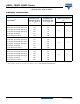
40HFL, 70HFL, 85HFL Series Fast Recovery Diodes Vishay High Power Products (Stud Version), 40 A/70 A/85 A FORWARD CONDUCTION PARAMETER SYMBOL Maximum average forward current at maximum case temperature IF(AV) Maximum RMS forward current TEST CONDITIONS 70HFL 85HFL UNITS 40 70 85 A 63 110 134 A 220 380 470 A 400 700 1100 420 730 1151 475 830 1308 500 870 1369 800 2450 6050 180° conduction, half sine wave 75 IF(RMS) Maximum peak repetitive forward current IFRM Sinusoid
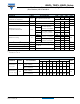
0HFL, 70HFL, 85HFL Series Vishay High Power Products Fast Recovery Diodes (Stud Version), 40 A/70 A/85 A THERMAL AND MECHANICAL SPECIFICATIONS PARAMETER SYMBOL Junction operating temperature range TEST CONDITIONS 40HFL 70HFL TJ - 40 to 125 Storage temperature range TStg - 40 to 150 Maximum thermal resistance, junction to case RthJC DC operation RthCS Mounting surface, smooth, flat and greased Maximum thermal resistance, case to heatsink 0.60 °C 0.30 0.25 3.
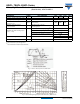
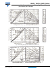
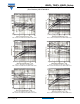
40HFL, 70HFL, 85HFL Series Fast Recovery Diodes Vishay High Power Products (Stud Version), 40 A/70 A/85 A Fig. 3 - Current Rating Nomogram (Rectangular Waveforms), 40HFL Series Fig. 4 - Current Rating Nomogram (Sinusoidal Waveforms), 70HFL Series 70HFL Fig. 5 - Current Rating Nomogram (Rectangular Waveforms), 70HFL Series Document Number: 93150 Revision: 25-May-09 For technical questions, contact: ind-modules@vishay.com www.vishay.
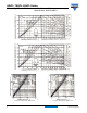
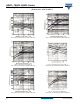
40HFL, 70HFL, 85HFL Series Vishay High Power Products Fast Recovery Diodes (Stud Version), 40 A/70 A/85 A 85HFL Fig. 6 - Current Rating Nomogram (Sinusoidal Waveforms), 85HFL Series 85HFL Fig. 7 - Current Rating Nomogram (Rectangular Waveforms), 85HFL Series Fig. 8 - Maximum High Level Forward Power Loss vs. Average Forward Current, 40HFL Series www.vishay.com 6 Fig. 9 - Maximum High Level Forward Power Loss vs.
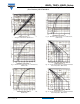
40HFL, 70HFL, 85HFL Series Fast Recovery Diodes Vishay High Power Products (Stud Version), 40 A/70 A/85 A Fig. 10 - Maximum High Level Forward Power Loss vs. Average Forward Current, 85HFL Series Fig. 13 - Maximum Forward Voltage vs. Forward Current, 85HFL Series Fig. 11 - Maximum Forward Voltage vs. Forward Current, 40HFL Series Fig. 14 - Average Forward Current vs. Maximum Allowable Case Temperature, 40HFL Series Fig. 12 - Maximum Forward Voltage vs. Forward Current, 70HFL Series Fig.
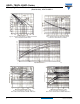
40HFL, 70HFL, 85HFL Series Vishay High Power Products Fast Recovery Diodes (Stud Version), 40 A/70 A/85 A Fig. 16 - Average Forward Current vs. Maximum Allowable Case Temperature, 85HFL Series Fig. 17 - Maximum Non-Repetitive Surge Current vs. Number of Current Pulses, All Series Fig. 18 - Maximum Transient Thermal Impedance, Junction to Case vs. Pulse Duration, All Series Fig. 19 - Typical Reverse Recovery Time vs. Rate of Fall of Forward Current, 40HFL...S02 Series www.vishay.com 8 Fig.
40HFL, 70HFL, 85HFL Series Fast Recovery Diodes Vishay High Power Products (Stud Version), 40 A/70 A/85 A Fig. 21 - Typical Reverse Recovery Time vs. Rate of Fall of Forward Current, 40HFL...S05 Series Fig. 24 - Typical Recovered Charge vs. Rate of Fall of Forward Current, 40HFL...S10 Series Fig. 22 - Typical Recovered Charge vs. Rate of Fall of Forward Current, 40HFL...S05 Series Fig. 25 - Typical Reverse Recovery Time vs. Rate of Fall of Forward Current, 70HFL...S02 Series Fig.
40HFL, 70HFL, 85HFL Series Vishay High Power Products Fast Recovery Diodes (Stud Version), 40 A/70 A/85 A Fig. 27 - Typical Reverse Recovery Time vs. Rate of Fall of Forward Current, 70HFL...S05 Series Fig. 30 - Typical Recovered Charge vs. Rate of Fall of Forward Current, 70HFL...S10 Series Fig. 28 - Typical Recovered Charge vs. Rate of Fall of Forward Current, 70HFL...S05 Series Fig. 31 - Typical Reverse Recovery Time vs. Rate of Fall of Forward Current, 85HFL...S02 Series Fig.
40HFL, 70HFL, 85HFL Series Fast Recovery Diodes Vishay High Power Products (Stud Version), 40 A/70 A/85 A Fig. 33 - Typical Reverse Recovery Time vs. Rate of Fall of Forward Current, 85HFL...S05 Series Fig. 35 - Typical Reverse Recovery Time vs. Rate of Fall of Forward Current, 85HFL...S10 Series Fig. 34 - Typical Recovered Charge vs. Rate of Fall of Forward Current, 85HFL...S05 Series Fig. 36 - Typical Recovered Charge vs. Rate of Fall of Forward Current, 85HFL...
Legal Disclaimer Notice Vishay Disclaimer All product specifications and data are subject to change without notice. Vishay Intertechnology, Inc., its affiliates, agents, and employees, and all persons acting on its or their behalf (collectively, “Vishay”), disclaim any and all liability for any errors, inaccuracies or incompleteness contained herein or in any other disclosure relating to any product.