
Instruction Manual

www.vishay.com For technical questions, contact: diodes-tech@vishay.com
Document Number: 94068
2 Revision: 25-Jul-08
HFA30PA60CPbF
Vishay High Power Products
HEXFRED
®
Ultrafast Soft Recovery Diode, 2 x 15 A
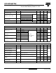
ELECTRICAL SPECIFICATIONS PER LEG (T
J
= 25 °C unless otherwise specified)
PARAMETER SYMBOL TEST CONDITIONS MIN. TYP. MAX. UNITS
Cathode to anode
breakdown voltage
V
BR
I
R
= 100 µA 600 - -
V
Maximum forward voltage V
FM
I
F
= 15 A
See fig. 1
-1.31.7
I
F
= 30 A - 1.5 2.0
I
F
= 15 A, T
J
= 125 °C - 1.2 1.6
Maximum reverse
leakage current
I
RM
V
R
= V
R
rated
See fig. 2
-1.010
µA
T
J
= 125 °C, V
R
= 0.8 x V
R
rated - 400 1000
Junction capacitance C
T
V
R
= 200 V See fig. 3 - 25 50 pF
Series inductance L
S
Measured lead to lead 5 mm from package body - 12 - nH
DYNAMIC RECOVERY CHARACTERISTICS PER LEG (T
J
= 25 °C unless otherwise specified)
PARAMETER SYMBOL TEST CONDITIONS MIN. TYP. MAX. UNITS
Reverse recovery time
See fig. 5, 10
t
rr
I
F
= 1.0 A, dI
F
/dt = 200 A/µs, V
R
= 30 V - 19 -
nst
rr1
T
J
= 25 °C
I
F
= 15 A
dI
F
/dt = 200 A/µs
V
R
= 200 V
-4260
t
rr2
T
J
= 125 °C - 70 120
Peak recovery current
See fig. 6
I
RRM1
T
J
= 25 °C - 4.0 6.0
A
I
RRM2
T
J
= 125 °C - 6.5 10
Reverse recovery charge
See fig. 7
Q
rr1
T
J
= 25 °C - 80 180
nC
Q
rr2
T
J
= 125 °C - 220 600
Peak rate of fall of
recovery current during t
b
See fig. 8
dI
(rec)M
/dt1 T
J
= 25 °C - 250 -
A/µs
dI
(rec)M
/dt2 T
J
= 125 °C - 160 -
THERMAL - MECHANICAL SPECIFICATIONS PER LEG
PARAMETER SYMBOL TEST CONDITIONS MIN. TYP. MAX. UNITS
Lead temperature T
lead
0.063” from case (1.6 mm) for 10 s - - 300 °C
Junction to case,
single leg conduction
R
thJC
--1.7
K/W
Junction to case,
both legs conducting
- - 0.85
Thermal resistance,
junction to ambient
R
thJA
Typical socket mount - - 40
Thermal resistance,
case to heatsink
R
thCS
Mounting surface, flat, smooth and greased - 0.25 -
Weight
-6.0- g
-0.21- oz.
Mounting torque
6.0
(5.0)
-
12
(10)
kgf · cm
(lbf · in)
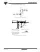
Marking device Case style TO-247AC (JEDEC) HFA30PA60C